Assembly - (Legacy) Traffic Light DT18-TL
Contents
Assembly - (Legacy) Traffic Light DT18-TL#
Assembly of the traffic light parts#
This section shows how to assemble the components from the laser cut traffic light parts.
Warning
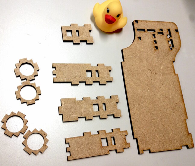
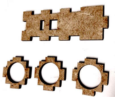
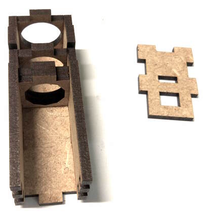
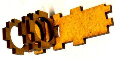
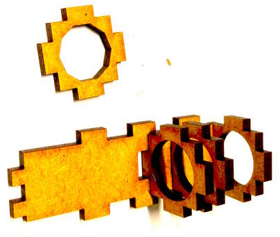
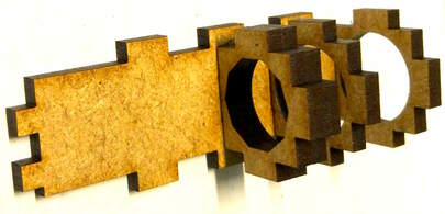
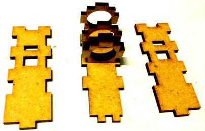
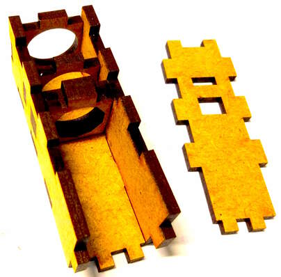
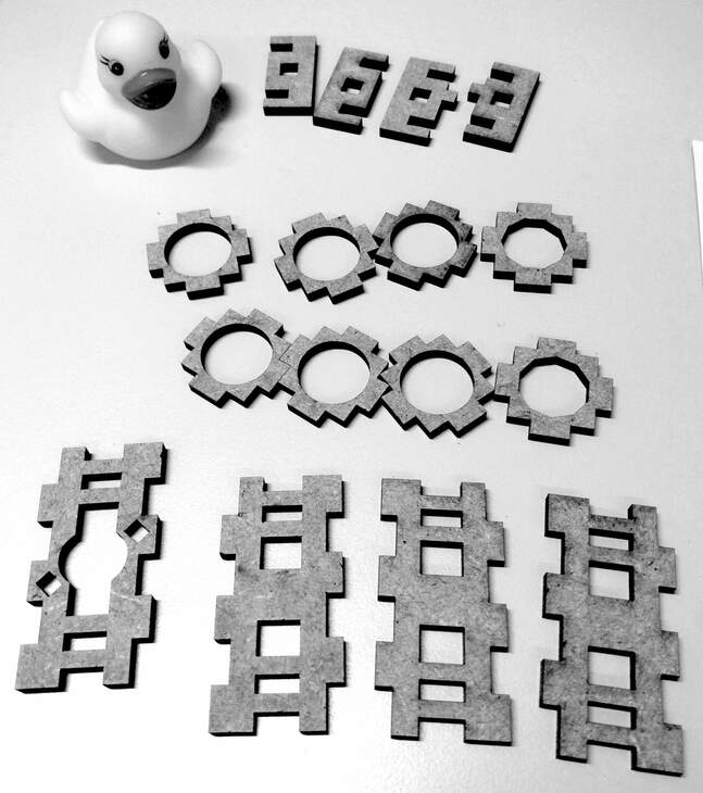
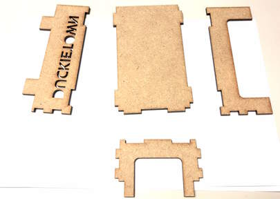
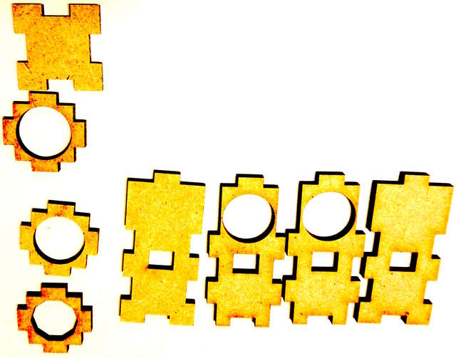
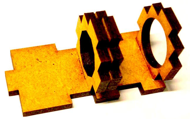
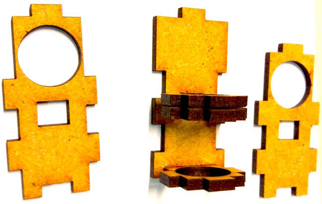
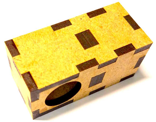
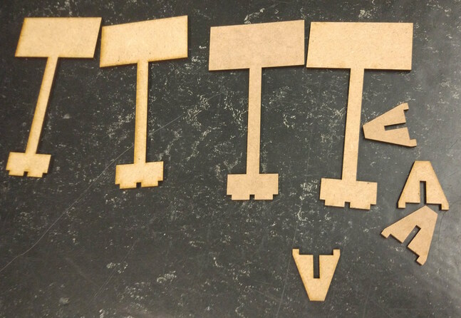
The small parts with the hole in the middle, i.e., the ones in the left of Fig. 58, are not all equal. Some have a round hole, others a polygonal hole. Double check you are using the right ones in the process (compare with the pics).
All parts should be glued together as showed in the pictures for enhanced structural stability.


Components of the traffic light#
Now that you have assembled the traffic light chassis, you are ready to add the electronics.
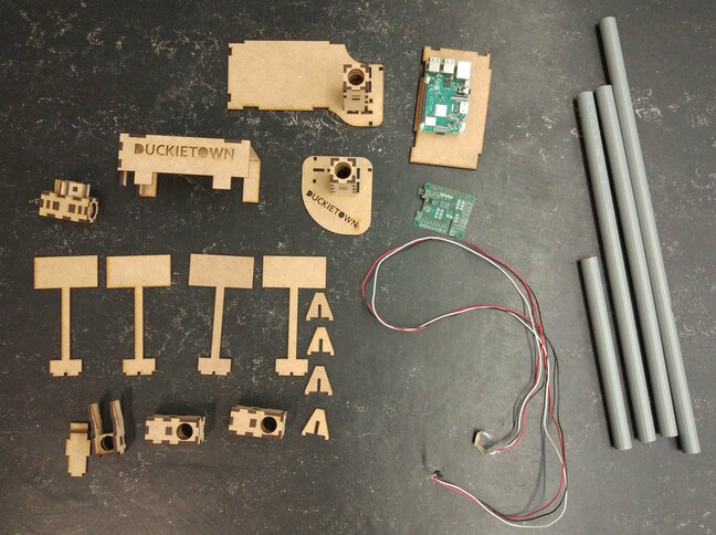
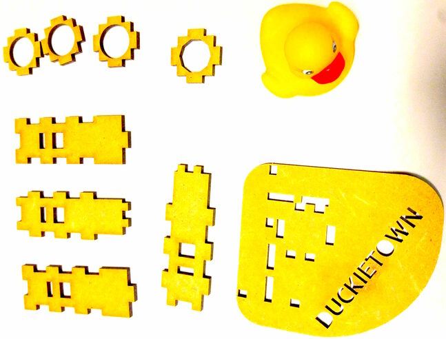
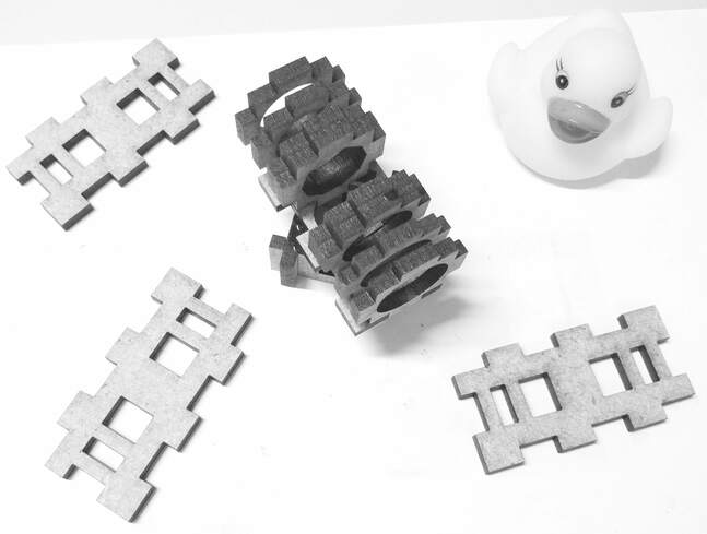
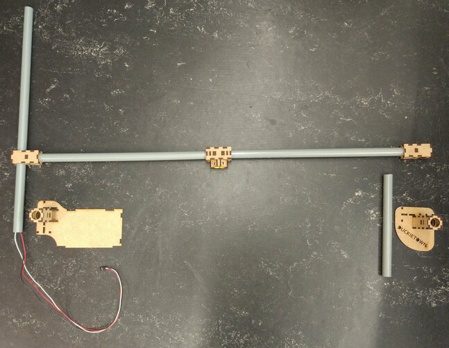
Fig. 60 Parts of a traffic light needed to complete these instructions.#
These components are needed for one traffic light:
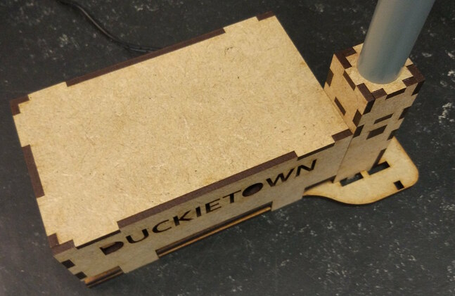
Tube holder with big ground plate
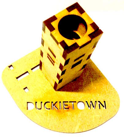
Tube holder with small ground plate (Duckietown)
Cable with soldered LED strip
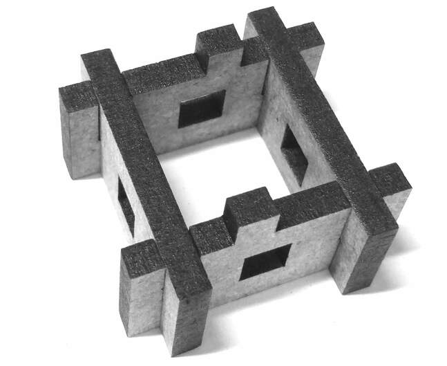
Joint module (2x)
Traffic light LED housing
Raspberry Pi base plate
Ground module cover (Duckietown)
Camera mount
Camera mount cover
Short tube
Medium tube (2x)
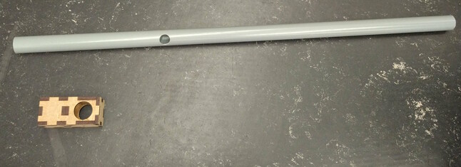
Long tube with hole at the side
Raspberry Pi
Raspberry Pi shield
M2.5x10 MF Nylon spacers (8x)
M2.5x8 Nylon screws (4x)
SD card with Duckietown software
USB cable
Ethernet cable
Additionally, the traffic light structure can host:
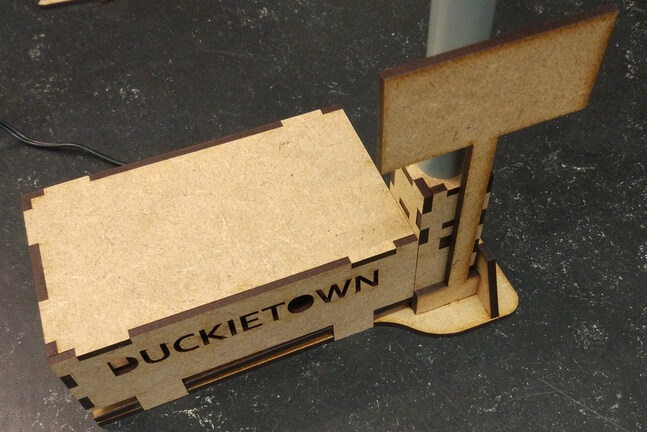
Traffic sign stands (4x)
Traffic sign stand supports (4x).
Assembling the Traffic Light#
Put the LEDs into the housing#
Bend the LED strip at an angle to reduce the chance that the exposed soldered wires short. The exposed part of the wires should not be in contact, especially when turning on the power.
Warning
The actual traffic light in your hands might vary slightly from the pictures above. In particular, the electrical cables could have different colors or be soldered in different positions. Take note of what each color cable is soldered to, as same will go go with same on the other end.
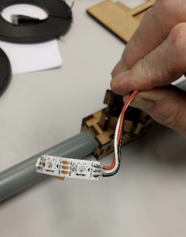
Fig. 61 Bent LED strip cable#
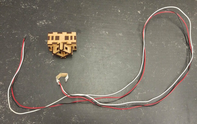
Fig. 62 Cable with soldered LED strip LED housing#

Carefully push the LEDs into the designated holes.
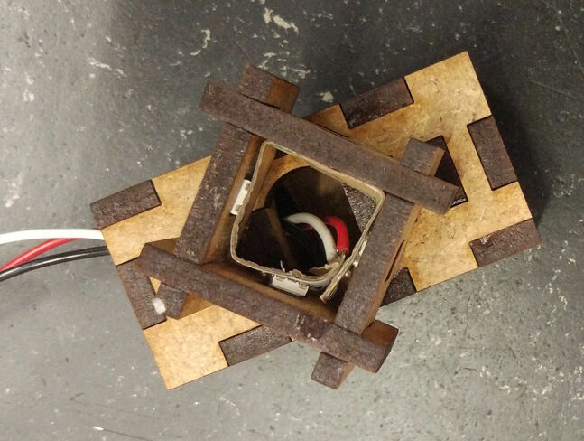
Fix the LEDs with some tape, don’t use glue.
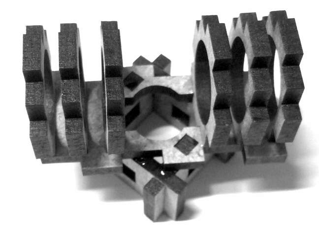
Connect the tubes#
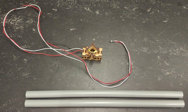
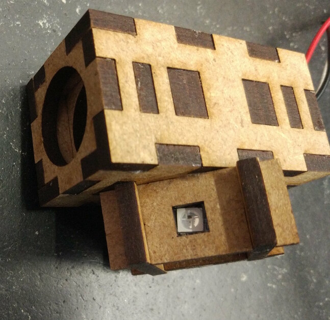
Fig. 63 Medium tubes and LED housing.#
Stick the tubes into the sides of the LED housing and pull the cable through one side.

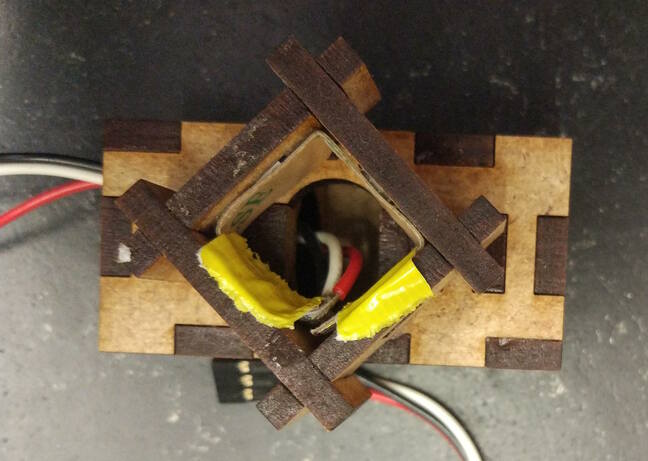
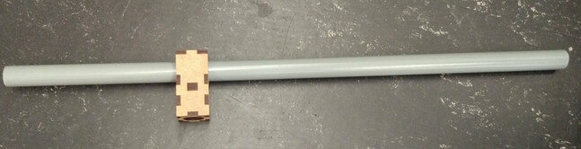
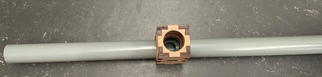
Add the joint modules on the side of the tube without the cable.
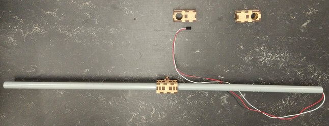
Mount the other joint module on the long tube, such that it aligns with the hole.
You can add additional tape under the joint modules to prevent them to slip down.
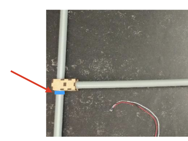
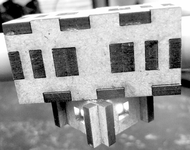
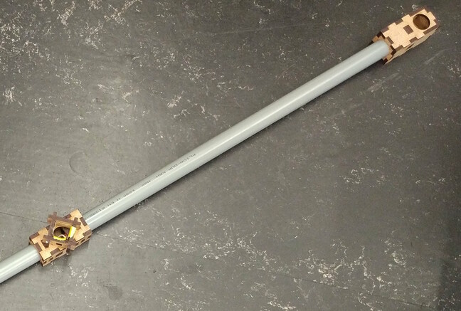
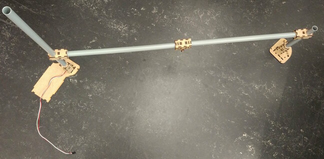
Fig. 64 Fully assembled traffic light.#
Pull the cable through longer tube and stick the tube into the joint module.
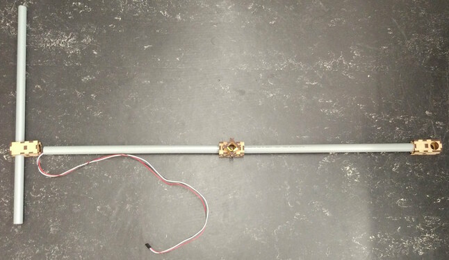
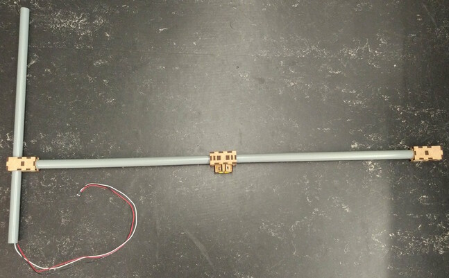
Put the tubes into the tube holders.
Connect the Raspberry Pi#
Use the spacers and the screws to mount the Raspberry Pi on the Raspberry Pi ground plate as shown in Fig. 65.
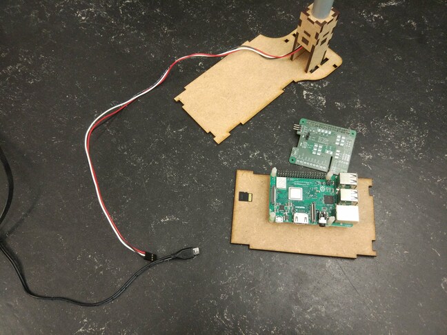
Fig. 65 Raspberry Pi mounted on ground plate#
Plug the shield on top of the Raspberry Pi.
Insert the SD card.
Connect the LED cable to the shield.

Connect the Ethernet cable.
Connect the USB cable.
If done correctly the LEDs should be on.

Close the ground module with the case.
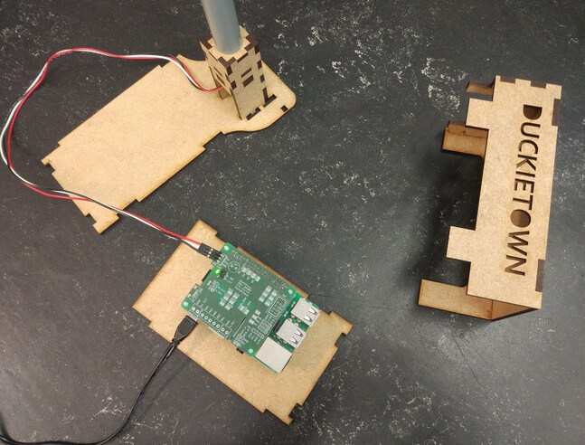
Fully assembled traffic light#
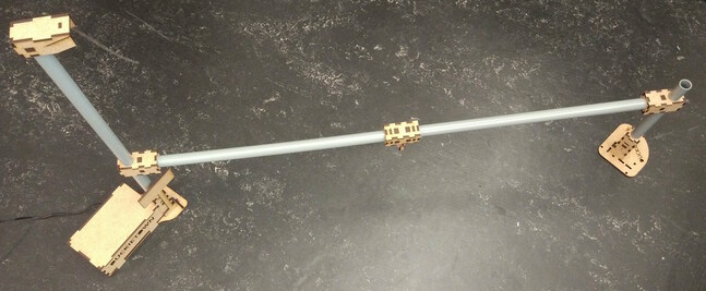
Fig. 66 Fully assembled traffic light.#
Place the traffic light at an intersection such that the LEDs are exactly in the middle and are facing each incoming lane perpendicularly.
You can verify the position is correct by verifying that Duckiebots at the red stop lines can see only one light blinking, and no reflections of LEDs facing other directions.
You can finally use the provided double-sided tape pads to fix the traffic light to the tiles.