Software Architecture
Contents
Software Architecture#
This section elaborates on all the DTPS and ROS nodes that run on the Duckiedrone.
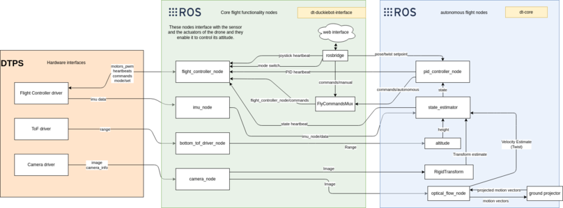
Fig. 58 Nodes composing the Duckiedrone autonomous flight stack#
Hardware interfaces#
These nodes interface with the hardware and expose its functionality through DTPS topics.
Camera driver#
The camera driver interfaces with the camera present on the drone, publishing compressed JPEG images and the camera calibration information.
Flight Controller Driver#
The flight controller node controls what mode the drone should be in based on the user input and on safety checks. For example, if any of the heartbeats stop publishing, the mode controller disarms the drone. If the mode is “ARMED” or “DISARMED”, the flight controller node sends static command values, but if the mode is “FLYING”, then the node sends the fly_commands topic to the flight controller board.
Flight Controller interfaces with the flight controller board to extract the IMU and battery data, and to publish the roll, pitch, yaw, and throttle commands which are used to control the attitude of the drone.
ToF driver#
Interfaces with the ToF sensors, publishing their range measurements.
Core flight functionality#
This group of nodes handles controlling the attitude of the drone, providing a pipeline to command thrust, roll, yaw and pitch.
IMU Node#
Exposes IMU data to ROS, according to REP145.
Flight Controller Node#
Exposes Flight Controller functionality to ROS.
ToF Node#
Exposes Range measurements as ROS topics.
FlyCommandsMux node#
Listens on two topics:
~manual~autonomous
If there is only one topic with valid commands (i.e. commands that are not too old), it uses that.
If both have valid inputs, depending on the DTParams specified in the __init__ function, masking is performed. By default, manual commands have higher priority. The parameters control which autonomous controls are passed through to the Flight Controller node.
rosbridge#
This node allows the web dashboard to communicate with ROS nodes on the drone by exposing topics through a websocket interface.
Autonomous flight functionality#
These nodes provide the capability to give a velocity or position command to the drone.
PID#
The PID controller node controls the flight of the drone by running a PID controller on the error calculated by the desired and current velocity and position of the drone.
State Estimator#
The State Estimator provides a container for the different state estimators (ema, UKF, …), taking as input the different measurements (altitude, velocity estimate, displacement estimate).
The different state estimators available are:
ema: uses an exponential moving average
The state typically consists of the x, y, z positions and velocities, and the yaw of the drone.
Optical Flow#
The Optical Flow node computes the optical flow motion vectors, sends them to the ground projector to be scaled based on the height and publishes the linear velocity calculated from the projected vectors.
Rigid Transform#
This node uses OpenCV to calculate the change in position of the drone using the camera by tracking the features in two consecutive images.
Topics naming#
Flight controller node:#
Topics:
    ~/flight_controller_node/battery

    ~flight_controller_node/commands

    ~/flight_controller_node/commands/executed

    ~/flight_controller_node/mode/current
Services:
    ~/flight_controller_node/set_mode

    ~/flight_controller_node/arm

    ~/flight_controller_node/calibrate_imu
IMU node:#
Topics:
    ~/imu_node/data

    ~/imu_node/raw
ToF node:#
Topics:
~/bottom_tof_driver_node/range