Beginner - Code Hierarchy
Contents
Beginner - Code Hierarchy#
In order to develop new functionality within the Duckietown ecosystem, you need to understand how the existing code is structured. This module will introduce you to the top-level structure as well as the references that can help you delve deeper.
While on the outside Duckietown seems to be all about a simple toy car with some duckies on top, once you dive deeper you will find out that it is much bigger on the inside. It’s not only about cars, but also boats and drones. And you can run the same code on a real Duckiebot, in simulation, or in a competitive AI Driving Olympics environment. You can also use some of the dozens of projects done before. As we clearly cannot cover everything in a concise way, this module will instead focus only on the code that runs on a Duckiebot during the standard demos, e.g. Lane Following and Indefinite Navigation.
Main images and repositories#
You probably noticed three container and image names popping up when you were running the demos, calibrating your
Duckiebot, or developing some of the previous exercises: dt-duckiebot-interface, dt-car-interface, and dt-core.
In this section, we’ll discuss what each image provides and how they interact.
Let’s first look at the bigger picture: the container hierarchy in Duckietown.
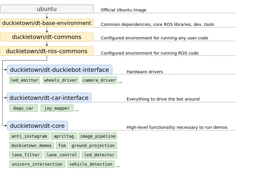
Fig. 13 The Docker image hierarchy#
As you can see in the above image, all three of the containers actually inherit the same container. Recall that ‘inheritance’ in a Docker images means that the ‘child’ image has a FROM statement with the ‘parent’ image in its Dockerfile. We typically say that the ‘child’ is based on ‘the parent’.
The image on which everything is based is ubuntu. It is simply the official Ubuntu image, with no added perks. Ubuntu 22.04 (Jammy Jellyfish) is used for the ente distribution of the Duckietown stack. Of course, as you can imagine, it is missing many key features that we would need. Also, it needs to be properly configured in order to work correctly with our software.
The duckietown/dt-base-environment adds many of the core libraries and configurations that we need. It installs development tools such as vim, git, nano and libraries for handling i2c devices, processing images, and efficiently doing linear algebra. It adds compilers, linkers, and libraries necessary for the compiling/building of software from source. Furthermore, we add pip and a bunch of handy python3 libraries, such as numpy, scipy, matplotlib, and smbus (used to communicate with motors, LEDs, etc). Finally, duckietown/dt-base-environment also provides the core ROS libraries, including rospy: ROS’s Python bindings. The version of ROS used is ROS Noetic Ninjemys.
Then, duckietown/dt-commons builds on top of duckietown/dt-base-environment. We provide a number of Duckietown libraries here that deal with files handling, infrastructure communication, and everything else that makes our development tools run smoothly. This image configures the environment so that the hostname resolution is correctly performed also, and ensures that the environment variables pertaining to the type of the robot, its hardware, and its configuration are all properly set. It also makes sure that all Python libraries are discoverable, and that ROS is setup correctly.
Building on top of it we have duckietown/dt-ros-commons, which has everything you need in order to start
developing code that directly works on your Duckiebot. However, as there are a few components that all Duckietown
ROS nodes share, it is convenient to package them in an image. These are duckietown-utils (a library with a number
of useful functions), duckietown_msgs (a ROS package that contains all the ROS message types used in Duckietown),
and DTROS. DTROS is a ‘mother’ node for all other nodes in Duckietown. You have already seen it while working
with ROS publishers and subscribers, but we will look at it in more detail soon.
The duckietown/dt-ros-commons is also the place where we keep protocols that are key for the communication between nodes found in different repositories. By placing them here, we ensure that all repositories work with the exact same protocol, and hence we prevent communication issues. Currently, the only protocol there is LED_protocol, which is used by the led_emitter_node in dt-duckiebot-interface, which emits LED-encoded messages, and by the led_detector_node in dt-core, which interprets the messages encoded in the LED flashing of other robots.
Finally, duckietown/dt-ros-commons packs another handy node: the ros_http_api_node. It exposes the ROS environment as an HTTP API. The ROS HTTP API runs by default on any Duckietown device and allows access to ROS topics, parameters, services, nodes, etc, over HTTP, which is an extremely portable interface. This is the technology behind our web-based interfaces that communicate with ROS, such as the Duckietown Dashboard.
We finally can focus on dt-duckiebot-interface, dt-car-interface, and dt-core. The first,
dt-duckiebot-interface, contains all the hardware drivers you need to operate your Duckiebot. In particular these are the drivers for the camera (in the camera_driver package), the ones for the motors (wheels_driver), and the LED drivers (led_emitter). Thanks to these nodes, you don’t need to interact with low level code to control your Duckiebot. Instead, you can simply use the convenient ROS topics and services provided by these nodes.
The dt-car-interface image provides additional basic functionality that is not on hardware level. It is all you need to be able to drive your Duckiebot around, in particular the parts that handle the commands sent by a (virtual) joystick (the joy_mapper package) and the forward and inverse kinematics that convert the desired robot movement to wheel commands (dagu_car package). It might not be immediately clear at first why these are not part of dt-duckiebot-interface or dt-core. In some use cases, e.g. for the demos or controlling a robot via a joystick, it is beneficial to have these two packages. For others, e.g. when deploying a completely different pipeline, e.g. end-to-end reinforcement learning, one would prefer to interact directly with the drivers. We will see more examples of use cases shortly.
The dt-core image provides all the high level robot behavior that you observe when running a demo. The image processing pipeline, decision-making modules, lane and intersection contollers, and many others reside there.
If you are curious to see all the ROS packages available in each of these images, you can check out the corresponding GitHub repositories:
Note
Make sure to look at the ente branches of these repositories! This is the most current release of the Duckietown
software.
As you will see in the nodes, there’s a lot of inline documentation provided.
Warning
Unfortunately, for the moment only dt-ros-commons, dt-duckiebot-interface, and dt-car-interface are
documented. We are working on providing similar level of documentation for dt-core as well.
Various configurations of the Duckietown codebase#
As we already mentioned, the Duckietown codebase can be used in various configurations: on a physical robot, in simulation, as an AI Driving Olympics submission, etc. Depending on how you want to deploy or use your code, you will be using different Docker images. Here we will take a look at a some of the most common use cases.
Driving with a (virtual) joystick#
If you only want to drive your Duckiebot around, you need the joy_mapper node that translates the joystick Joy messages to car command messages, the kinematics node that in turn converts these to wheel command messages, and the wheels_driver node that controls the motors. So the dt-duckiebot-interface and dt-car-interface images are enough.
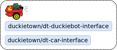
Fig. 14 Driving with a virtual joystick.#
Driving through the Dashboard#
As you saw when setting up your Duckiebot, the Dashboard and the Compose interface also provide manual driving functionality. For this, one needs the same images as before, of course together with the Dashboard image itself:
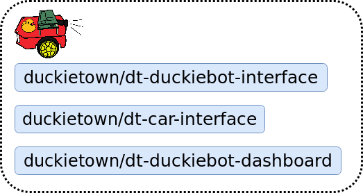
Fig. 15 Driving through the Dashboard.#
Running a demo on a Duckiebot#
Running a demo requires to drive around together with the high-level processing and logic that reside in the dt-core image:
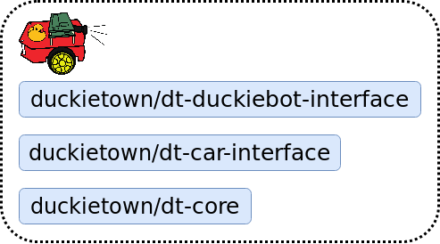
Fig. 16 Running a demo on a Duckiebot.#
Running a demo in simulation#
A demo can also be executed in simulation. In this case, instead of using the hardware drivers dt-duckiebot-interface provides, we substitute them with the simulator interface:
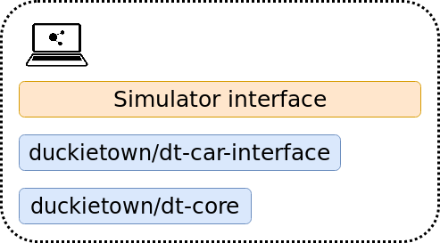
Fig. 17 Running a demo in simulation.#
Evaluating AIDO submissions in simulation#
An AI Driving Olympics submission is essentially a container that receives image data and outputs wheel commands. Therefore, it can replace the dt-car-interface and dt-core images and still use the same simulator framework. This can also be done in the cloud, and that is exactly how AIDO submissions get evaluated in simulation on the challenges server.
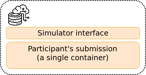
Fig. 18 Evaluating an AIDO submission in simulation.#
Evaluating AIDO submissions on a Duckiebot#
The same submission image, with not a single change, can be also tested on a real Duckiebot! Simply substitute the simulator with the dt-duckiebot-interface. As the containers don’t need to run on the same device, we can also use much powerful computers (also state-of-the-art GPUs) when testing submissions. This is the way that AIDO submissions get evaluated in Autolabs. In this way, even if you don’t have a Duckiebot, you can develop your submission in simulation, then submit it to be evaluated in simulations on the challenges server, and if it performs well, you can request remote evaluation on a real Duckiebot in a Duckietown Autolab!
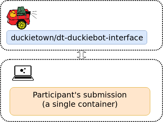
Fig. 19 Evaluating an AIDO submission on a Duckiebot.#