Getting the Duckiebot hardware
Contents
Getting the Duckiebot hardware#
What you will need
Knowledge of Duckiebot hardware configurations
What you will get
Parts to assemble a Duckiebot.
Foreword#
You can acquire Duckiebots in two ways:
“One click” solution (
DB18and above): you can source complete hardware kits on the Duckietown project online store. These kits are tested to work with Duckietown software, are guaranteed to work, and come with a 12 months warranty. This is the officially supported and recommended path to getting started with Duckietown.Do it yourself (
DB17): theDB17Duckiebot configuration is made of components that you can source independently. This configuration is no longer actively supported, but you can find the bill of materials for this DIY approach below.
Acquiring the parts for a DB17#
Here, we provide a link to all bits and pieces that are needed to build a DB17-jwd Duckiebot, along with the price tag.
In general, keep in mind that:
The links might expire, or the prices might vary.
Shipping times and fees vary, and are not included in the prices shown below.
International deliveries are subject to additional custom clearances and import fees.
Substitutions are OK for the mechanical components, and not OK for all the electronics, unless you are OK in writing some software. Limited technical support will be offered for hardware customizations.
Buying the parts for more than one Duckiebot makes each one cheaper than buying only one.
For some components, the links we provide contain more bits than actually needed.
DB17 Bill of materials#
Item |
Cost (USD) |
|---|---|
20 |
|
39 |
|
4 |
|
2 |
|
39 |
|
3 |
|
7.50 |
|
10 |
|
6 |
|
22.50 |
|
2.50/piece |
|
25 |
|
0.06/piece |
|
0.02/piece |
|
0.05/piece |
|
9 |
|
Wireless Adapter (5 GHz) ( |
25 |
Joypad ( |
10.50 |
Tiny 32GB USB Flash Drive ( |
10 |
PWM/Servo HAT ( |
17.50 |
Power Cable ( |
7.80 |
Male-Male Jumper Wire ( |
1.95 |
8 M3x10 pan head screws ( |
7 |
8 M3 nuts ( |
7 |
Bumpers set ( |
7 (custom made) |
Bumper bracers set ( |
7 (custom made) |
LEDs ( |
10 |
LED HAT ( |
9/piece (but 3 pieces minimum) |
20 Female-Female Jumper Wires (300mm) ( |
8 |
4 4 pin female header ( |
0.60/piece |
12 pin male header ( |
0.48/piece |
2 16 pin male header ( |
0.61/piece |
3 pin male header ( |
0.10/piece |
2 pin female shunt jumper ( |
2/piece |
40 pin female header ( |
1.50 |
5 200 Ohm resistors ( |
0.10/piece |
10 130 Ohm resistors ( |
0.10/piece |
20 |
|
Total for |
193 |
Total for |
218 |
Total for |
203 |
Total for |
203 |
Total for |
238 |
Total for |
367 |
Chassis#
We selected the Magician Chassis as the basic chassis for the robot (The “Magician” chassis was very popular. It is used in DB17 through DB19 Duckiebot models.).
We chose it because it has a double-decker configuration, and so we can put the battery in the lower part.
The chassis pack includes 2 DC motors and wheels as well as the structural part, in addition to a screwdriver and several necessary mechanical bits (standoffs, screws and nuts).
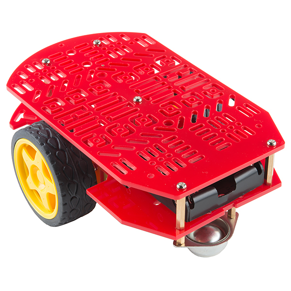
Fig. 7 The “Magician” chassis was very popular. It is used in DB17 through DB19 Duckiebot models.#
Raspberry Pi 3 - Model B#
Note: It is recommended to upgrade to Raspberry Pi 3 model B+. In this case the 5 GHz wireless adapter is no longer necessary.
The Raspberry Pi is the central computer of the Duckiebot. Duckiebots use Model B (Fig. 8), a small but powerful computer.
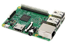
Fig. 8 The Raspberry Pi 3 Model B is a 1.2GHz, 64-bit quad-core ARMv8 CPU, 1GB RAM little computer.#
Power Supply#
We want a hard-wired power source (5VDC, 2.4A, Micro USB) to supply the Raspberry Pi (The power supply.) while not driving. This charger can double down as battery charger as well.
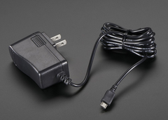
Fig. 9 The power supply.#
Heat Sinks#
The Raspberry Pi will heat up significantly during use. It is recommended adding heat sinks, as in The heat sinks.. Since we will be stacking HATs on top of the Raspberry Pi with 15 mm standoffs, the maximum height of the heat sinks should be well below 15 mm. The chip dimensions are 15x15mm and 10x10mm.
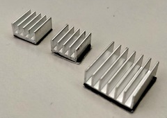
Fig. 10 The heat sinks.#
Class 10 MicroSD Card#
The MicroSD card (The MicroSD card.) is the hard disk of the Raspberry Pi. 16 GB of capacity are sufficient for the system image.
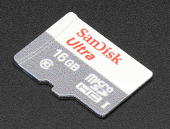
Fig. 11 The MicroSD card.#
Mirco SD card reader#
A microSD card reader (The Mirco SD card reader.) is useful to copy the system image to a Duckiebot from a computer to the Raspberry Pi microSD card, when the computer does not have a native SD card slot.
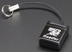
Fig. 12 The Mirco SD card reader.#
Camera#
The Camera is the main sensor of the Duckiebot. All versions equip a 5 Mega Pixels 1080p camera with wide field of view (\(160^\circ\)) fisheye lens (The Raspberry Pi camera with fisheye lens.).
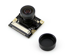
Fig. 13 The Raspberry Pi camera with fisheye lens.#
Camera Mount#
The camera mount (The camera mount.) serves to keep the camera looking forward at the right angle to the road (looking slightly down). The front cover is not essential.
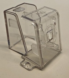
Fig. 14 The camera mount.#
The assembled camera (without camera cable), is shown in (The camera on its mount.).
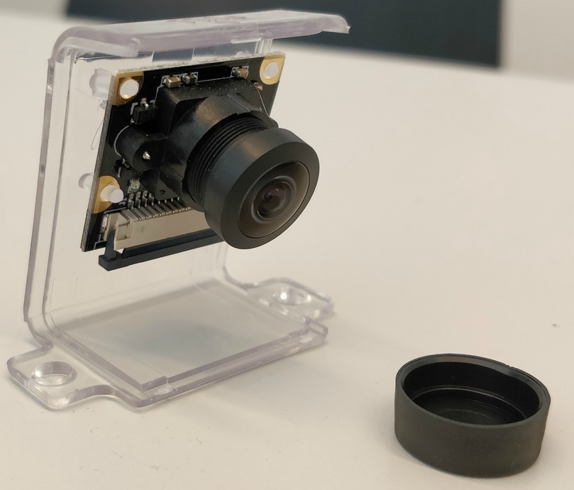
Fig. 15 The camera on its mount.#
300mm Camera Cable#
A longer (300 mm) camera cable A 300 mm camera cable for the Raspberry Pi. makes assembling the Duckiebot easier, allowing for more freedom in the relative positioning of camera and computational stack.
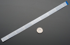
Fig. 16 A 300 mm camera cable for the Raspberry Pi.#
DC Motor HAT#
We use the DC Stepper motor HAT (The stepper motor HAT.) to control the DC motors that drive the wheels. This item will require soldering to be functional. This HAT has dedicate PWM and H-bridge for driving the motors.
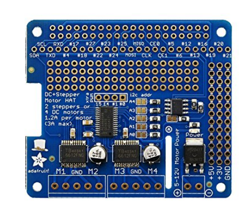
Fig. 17 The stepper motor HAT.#
Stacking Headers#
We use a long 20x2 GPIO stacking header (The stacking headers.) to connect the Raspberry Pi with the DC Motor HAT. This item will require soldering to be functional.
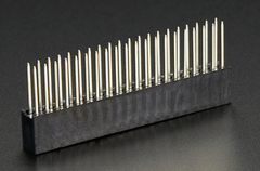
Fig. 18 The stacking headers.#
Battery#
The battery (The battery.) provides power to the Duckiebot.
We choose this battery because it has a good combination of size (to fit in the lower deck of the Magician Chassis), high output amperage (2.4A and 2.1A at 5V DC) over two USB outputs, a good capacity (10400 mAh) at an affordable price. The battery linked in the table above comes with two USB to microUSB cables.
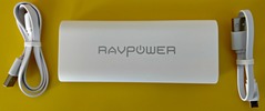
Fig. 19 The battery.#
Standoffs, Nuts and Screws#
We use non electrically conductive standoffs (M2.5 12mm F 6mm M), nuts (M2.5), and screws (M2.5x10mm) to hold the Raspberry Pi to the chassis and the HATs stacked on top of the Raspberry Pi.
The Duckiebot requires 8 standoffs, 4 nuts and 4 screws.
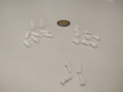
Fig. 20 Standoffs, Nuts and Screws.#
Zip Ties#
Two 300x5mm zip ties are needed to keep the battery at the lower deck from moving around.
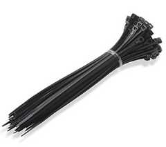
Fig. 21 The zip ties.#
Configuration DB17-w#
Wireless Adapter (5 GHz)#
The Edimax AC1200 EW-7822ULC 5 GHz wireless adapter (The Edimax AC1200 EW-7822ULC WiFi adapter.) boosts the connectivity of the Duckiebot, especially useful in busy Duckietowns (e.g., classroom). This additional network allows easy streaming of images.
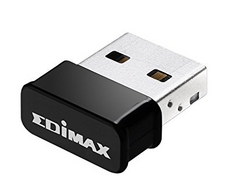
Fig. 22 The Edimax AC1200 EW-7822ULC WiFi adapter.#
This component is not necessary if upgrading to Raspberry Pi 3 Model B+.
Configuration DB17-j#
Joypad#
The joypad is used to manually remote control the Duckiebot. Any 2.4 GHz wireless controller (with a tiny USB dongle) will do.
The model linked in the table (A Wireless joypad.) does not include batteries.
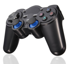
Fig. 23 A Wireless joypad.#
Requires: 2 AA 1.5V batteries (Batteries.) not included in the bill of materials.
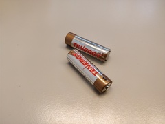
Fig. 24 Batteries.#
Configuration DB17-d#
Tiny 32 GB USB Flash Drive#
In configuration DB17-d, the Duckiebot is equipped with an “external” hard drive (The tiny 32 GB USB flash drive.). This add-on is very convenient to store logs during experiments and later port them to a workstation for analysis. It provides storage capacity and faster data transfer than the MicroSD card.
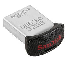
Fig. 25 The tiny 32 GB USB flash drive.#
Configuration DB17-l#
LEDs#
This Duckiebot is equipped with 5 RGB LEDs (The DB17 RGB LEDs.). LEDs can be used to signal to other Duckiebots, or just make fancy patterns.
The pack of LEDs linked in the table above holds 10 LEDs, enough for two Duckiebots.
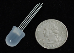
Fig. 26 The DB17 RGB LEDs.#
LED HAT#
The LED HAT (The LED HAT.) provides an interface for our RGB LEDs and the computational stack. This board is a daughterboard for the Adafruit 16-Channel PWM/Servo HAT, and enables connection with additional gadgets such as ADS1015 12 Bit 4 Channel ADC, Monochrome 128x32 I2C OLED graphic display, and Adafruit 9-DOF IMU Breakout - L3GD20H+LSM303. This item will require soldering.
This board is custom designed and can only be ordered in minimum runs of 3 pieces. The price scales down quickly with quantity, and lead times may be significant, so it is better to buy these boards in bulk.
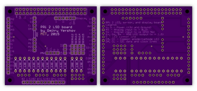
Fig. 27 The LED HAT.#
PWM/Servo HAT#
The PWM/Servo HAT (The PWM-Servo HAT.) mates to the LED HAT and provides the signals to control the LEDs, without taking computational resources away from the Rasperry Pi itself. This item will require soldering.
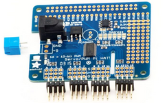
Fig. 28 The PWM-Servo HAT.#
Power Cable#
To power the PWM/Servo HAT from the battery, we use a short (30cm) angled male USB-A to 5.5/2.1mm DC power jack cable (The 30cm angled USB to 5.5/2.1mm power jack cable.).
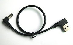
Fig. 29 The 30cm angled USB to 5.5/2.1mm power jack cable.#
Male-Male Jumper Wires#
The Duckiebot needs one male-male jumper wire (Male-male jumper wires.) to power the DC Stepper Motor HAT from the PWM/Servo HAT.
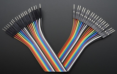
Fig. 30 Male-male jumper wires.#
Female-Female Jumper Wires#
20 Female-Female Jumper Wires (Female-female jumper wires.) are necessary to connect 5 LEDs to the LED HAT.
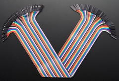
Fig. 31 Female-female jumper wires.#
Bumpers#
These bumpers are designed to keep the LEDs in place and are therefore used only in configuration DB17-l. They are custom designed parts, so they must be produced and cannot be bought. We used laser cutting facilities.
Headers, resistors and jumper#
Upgrading DB17 to DB17-l requires several electrical bits: 5 of 4 pin female header, 2 of 16 pin male headers, 1 of 12 pin male header, 1 of 3 pin male header, 1 of 2 pin female shunt jumper, 5 of 200 Ohm resistors and finally 10 of 130 Ohm resistors.
These items require soldering.
Caster (DB17-c)#
The caster (The caster wheel.) is an DB17-c component that substitutes the steel omni-directional wheel that comes in the Magician Chassis package. Although the caster is not essential, it provides smoother operations and overall enhanced Duckiebot performance.
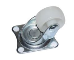
Fig. 32 The caster wheel.#
To assemble the caster at the right height we will need to purchase:
4 standoffs (M3 12mm F-F) (Standoffs for caster wheel.),
8 screws (M3x8mm) (Screws for caster wheel.), and
8 split lock washers (Split lock washers for caster wheel.).
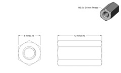
Fig. 33 Standoffs for caster wheel.#
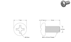
Fig. 34 Screws for caster wheel.#
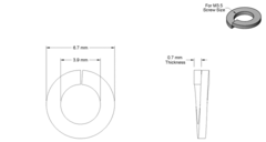
Fig. 35 Split lock washers for caster wheel.#
Note
The caster wheel use is to be considered experimental and has been dropped in official configurations starting from DB18.