Assembly Instructions (DB21J)
Contents
Assembly Instructions (DB21J)#
This section describes the assembly procedure for your Duckiebot DB21J.
What you will need
The components for a Duckiebot
DB21-J4(available on the Duckietown online store).
What you will get
An assembled Duckiebot DB21J.
What’s in the box and assembly video (DB21M)
Duckiebot DB21M unpacking and assembly from Duckietown on Vimeo. Note this video is not from a DB21J4, and details differ.
Preliminary steps#
Unboxing#
Unbox all of the components within your Duckiebox and lay them out on a flat surface.
Ensure that you have well-lit, uncluttered space to work on.
Although not necessary, a small (M2.5) wrench and pliers may ease some passages.
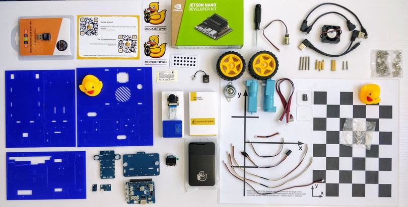
Fig. 11 The contents of a DB21J Duckiebox.#
Note
Your Duckiebot chassis may be under the white protective foam inside the Duckiebox. To reach it, pull the white foam out of the box after removing everything else. Note that the upper part of the inside foam has several side pockets in addition to a main compartment where components are located.
Plastic cover#
Peel off the plastic covers from both sides of every chassis component.
Connecting components#
Verify each connecting component (screws, nuts and stand-offs) before using them as this may prevent undesirable effects (e.g., nylon screws prevent electrical shorts, bigger screws may damage the chassis, etc.). There are also shorter screws, which can be used in some cases.
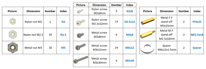
Fig. 12 Connecting components.#
HUT#
The HUT an electronics board containing the connectors for various sensors (e.g., fan, motors, top button, etc.) that is mounted to the Jetson Nano.
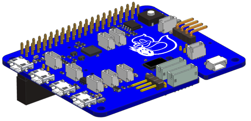
Fig. 13 The HUT.#
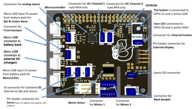
Fig. 14 The HUT’s components.#
Charging the Duckiebattery via the HUT#
This preliminary step allows the Duckiebattery to begin charging while confirming the functionality of the HUT.
To charge the Duckiebattery via the HUT:
Connect the Duckiebattery to the HUT as shown below and make sure that a green LED on the HUT is lit.
Wait
30 minand then press the button on the Duckiebattery.Check that the state of charge LEDs on the Duckiebattery start blinking.
Leave this setup until the Duckiebattery is charged (this may take up to
5 h).
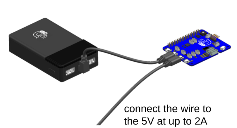
Fig. 15 The Duckiebattery charging via the HUT.#
Note
For more information on the Duckiebattery, follow The Duckiebattery (DB-C-DBatt).
Camera assembly#
This section describes the steps to assemble the camera assembly.
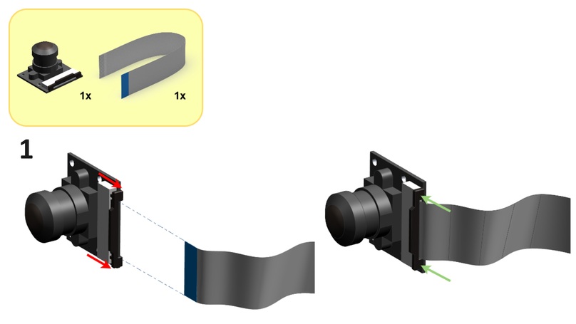
Step 1#
Substeps:
Gently open but do not remove the camera cable connector on the camera PCB as shown below.
Connect the camera cable to the camera cable connector on the camera PCB such that the pins on the camera cable come into contact with those in the camera cable connector on the camera PCB as shown below (the blue strip on the camera cable should face away from the camera PCB).
Close the camera cable connector on the camera PCB as shown below.
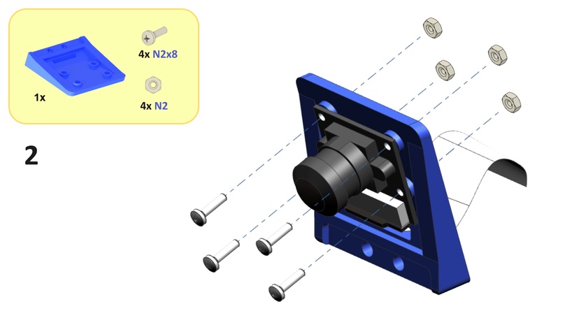
Step 2#
Substeps:
From the front side of the camera holder, feed the camera cable through the slot in the camera holder as shown below.
Screw the camera PCB onto the front side of the camera holder using four
N2x8screws and fourN2nuts as shown below.
Bottom assembly#
This section describes the steps to assemble the bottom assembly.
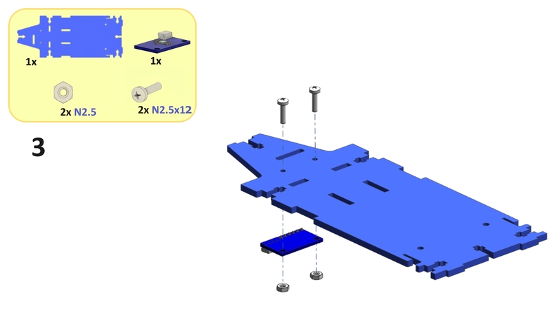
Step 3#
Screw the IMU PCB onto the top side of the bottom plate using two N2.5x12 screws and two N2.5 nuts as shown below.
Step 4#
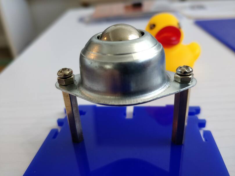
Screw two FF3x25 standoffs onto the top side of the omni wheel using two M3x8 screws as shown below.
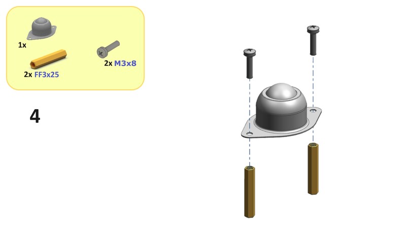
Tip
For this step and Step 5, try using shorter screws if the suggested screws do not fully insert into the standoffs.
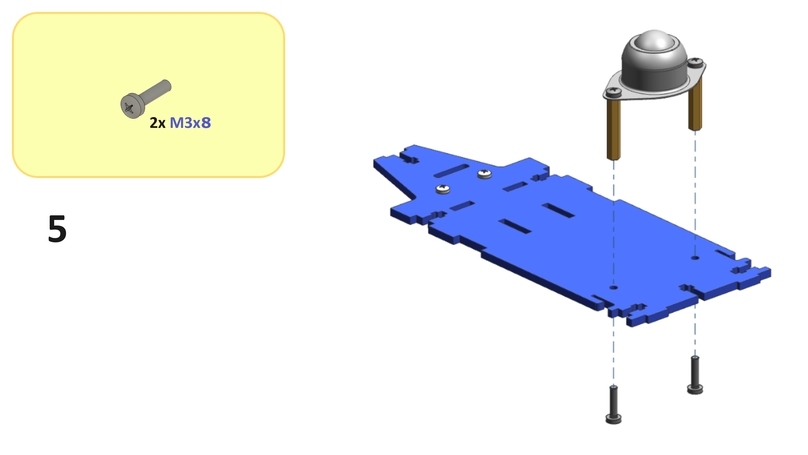
Step 5#
Screw the standoffs from Step 4 onto the bottom side of the bottom plate using two M3x8 screws as shown below.
Step 6#
Place four M3 nuts into the bottom plate as shown below.
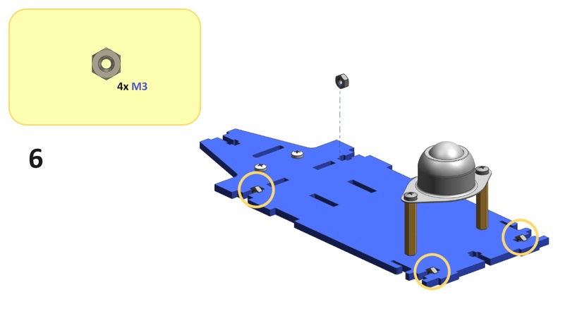
Tip
Occasionally, manufacturing tolerances (on the nut and the chassis) may prevent a flush fit. Try using a different nut or changing its orientation to solve this problem. It may also be convenient to use pliers.
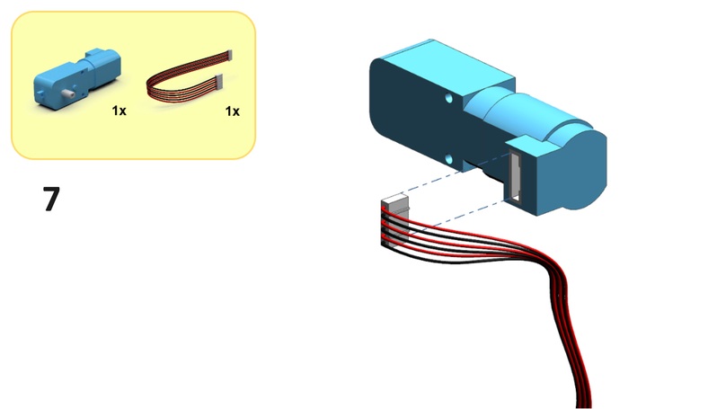
Step 7#
Connect a motor cable to a motor as shown below.
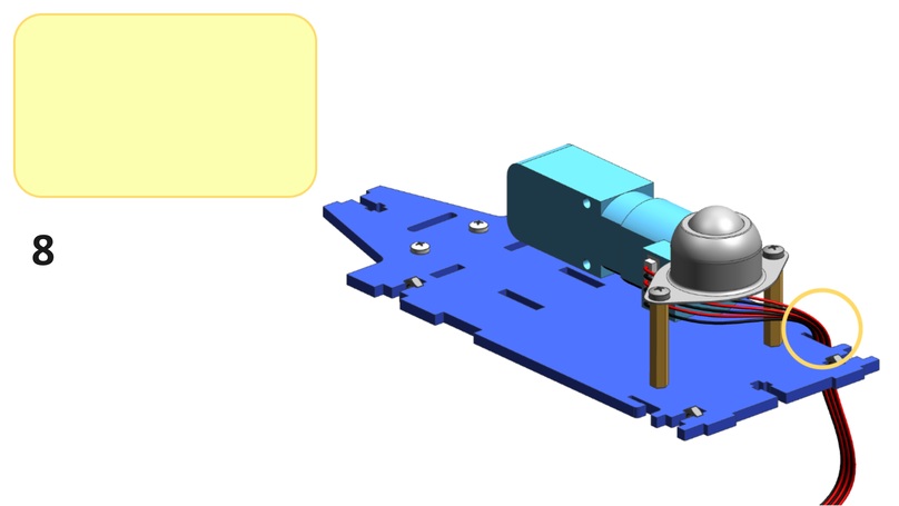
Step 8#
Substeps:
Place the motor from Step 7 onto the bottom left side of the bottom plate as shown below.
From the front side of the bottom plate, feed the motor cable from Step 7 between the standoffs from Step 4 as shown below.
From the bottom side of the bottom plate, feed the motor cable through the back left slot in the bottom plate as shown below.
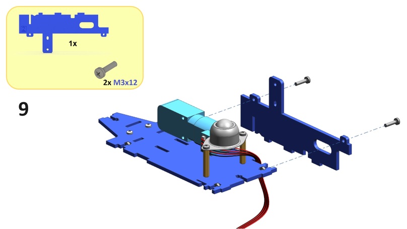
Step 9#
Screw a bottom side plate onto the left side of the bottom plate using two M3x12 screws and two M3 nuts from Step 6 as shown below.
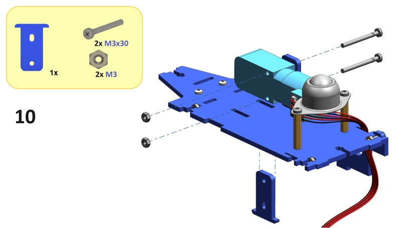
Step 10#
Substeps:
From the top side of the bottom plate, feed a motor support through the middle left slot in the bottom plate as shown below.
Screw the motor onto the left side of the motor support and right side of the bottom side plate from Step 9 using two
M3x30screws and twoM3nuts as shown below.
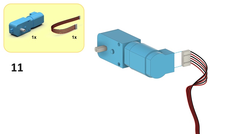
Step 11#
Connect the other motor cable to the other motor as shown below.
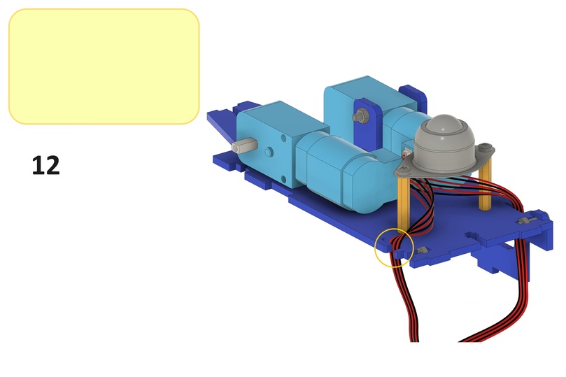
Step 12#
Substeps:
Place the motor from Step 11 onto the bottom right side of the bottom plate as shown below.
From the front side of the bottom plate, feed the motor cable from Step 11 between the standoffs from Step 4 as shown below.
From the bottom side of the bottom plate, feed the motor cable through the back right slot in the bottom plate as shown below.
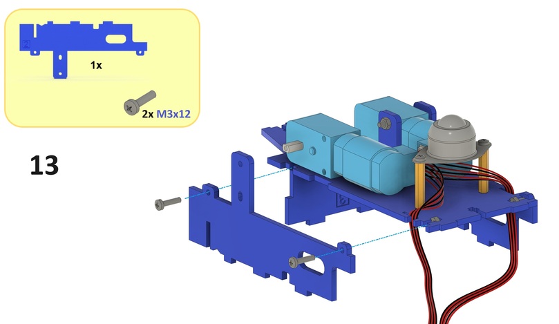
Step 13#
Screw the other bottom side plate onto the right side of the bottom plate using two M3x12 screws and two M3 nuts from Step 6 as shown below.
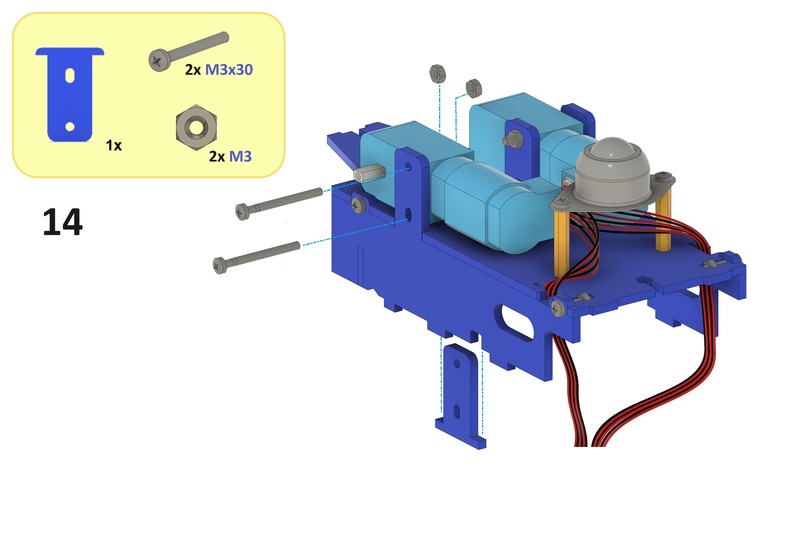
Step 14#
Substeps:
From the top side of the bottom plate, feed the other motor support through the middle right slot in the bottom plate as shown below.
Screw the motor onto the right side of the motor support and left side of the bottom side plate from Step 13 using two
M3x30screws and twoM3nuts as shown below.
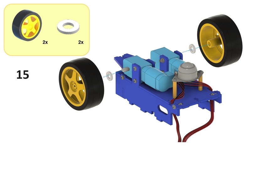
Step 15#
Substeps:
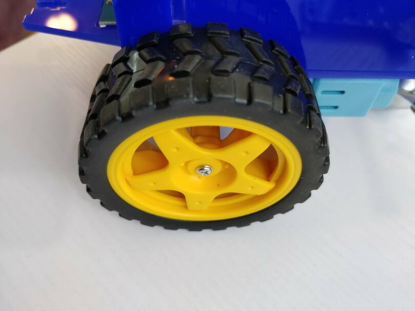
Place a spacer onto each motor axle such that the spacer sits flush against the motor housing as shown below.
Place a wheel onto each motor axle such that the wheel sits flush against the respective spacer as shown below.
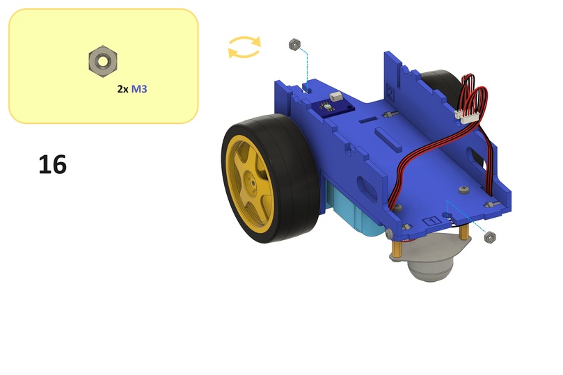
Step 16#
Place two M3 nuts into the bottom plate as shown below.
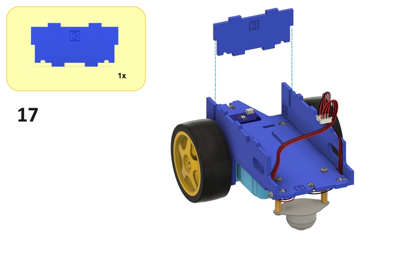
Step 17#
Place the Duckiebattery separator into the slots in the bottom plate and bottom side plates as shown below.
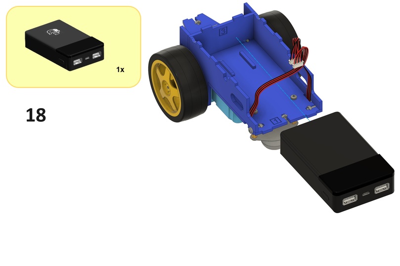
Step 18#
Attention
Remove any USB cables connected to the Duckiebattery.
Place the Duckiebattery onto the top sides of the motor supports and the screws that are attaching the standoffs from Step 4 to the bottom plate as shown below (the Duckietown logo should face away from the bottom plate).
Attention
Verify that every component other than the cables, omni wheel sphere and motor axles is fixed. Otherwise, gently tighten the screws of the loose components.
Computation unit#
This section describes the steps to assemble the computation unit.
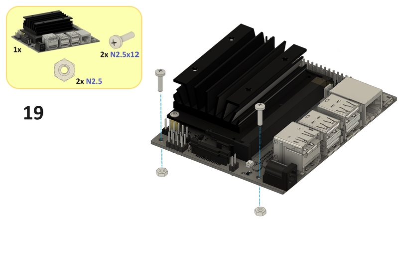
Step 19#
Screw two N2.5 nuts onto the bottom side of the Jetson Nano using two N2.5x12 screws as shown below.
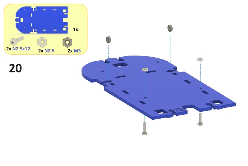
Step 20#
Substeps:
Place two
M3nuts into the middle plate as shown below.Screw two
N2.5nuts onto the top side of the middle plate using twoN2.5x12screws as shown below.
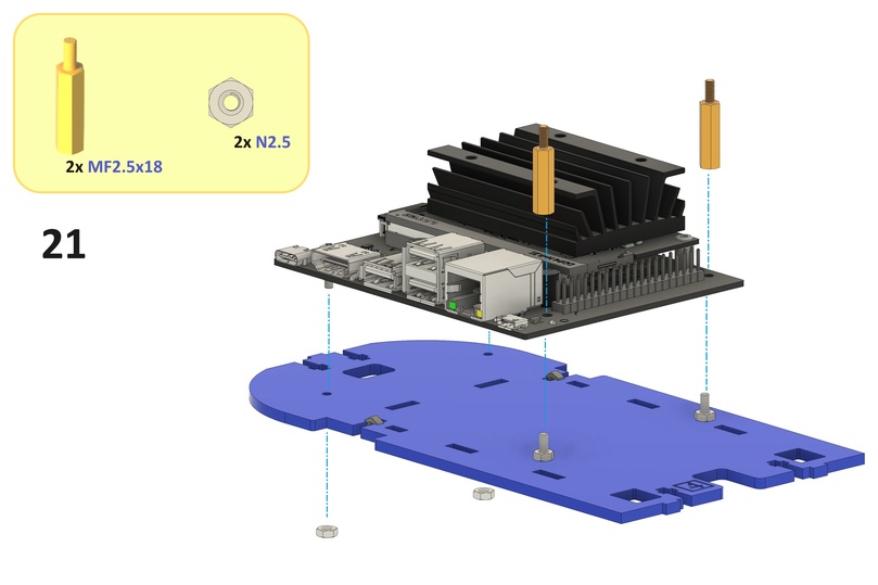
Step 21#
Substeps:
Place the Jetson Nano onto the screws from Step 20 as shown below.
Screw two
N2.5nuts onto the bottom side of the middle plate using the screws from Step 19 as shown below.Screw two
MF2.5x18standoffs onto the top side of the Jetson Nano using the screws from Step 20 as shown below.
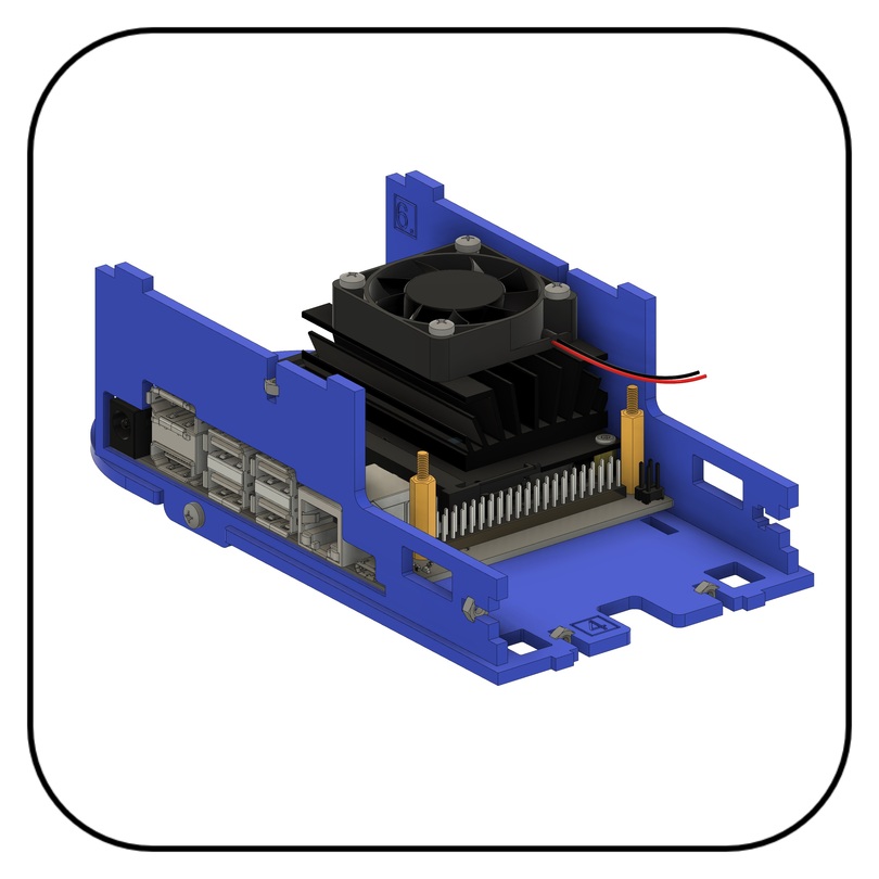
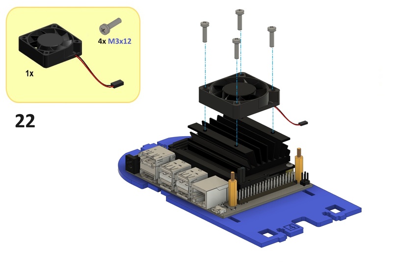
Step 22#
Screw the fan onto the heat sink of the Jetson Nano using four M3x12 screws as shown below.
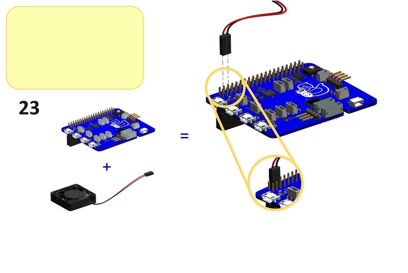
Step 23#
Substeps:
Connect the red fan cable to a GPIO pin labeled
5Von the HUT as shown below (or a GPIO pin labeled3.3Von the HUT for a lower fan speed and less noise).Connect the black fan cable to a GPIO pin labeled
GNDon the HUT as shown below.

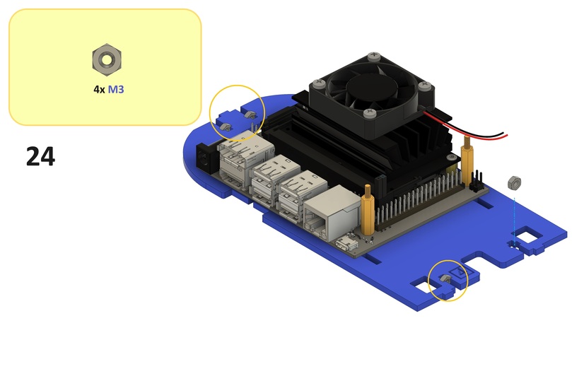
Step 24#
Place four M3 nuts into the middle plate as shown below.
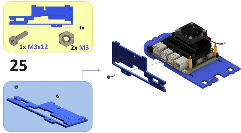
Step 25#
Substeps:
Place two
M3nuts into the left top side plate as shown below.Screw the left top side plate onto the left side of the middle plate using an
M3x12screw as shown below.
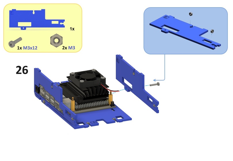
Step 26#
Substeps:
Place two
M3nuts into the right top side plate as shown below.Screw the right top side plate onto the right side of the middle plate using an
M3x12screw as shown below.
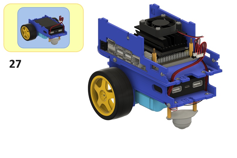
Step 27#
From the bottom side of the middle plate, place the Duckiebattery separator and bottom side plates into the slots in the middle plate as shown below.
Back assembly#
This section describes the steps to assemble the back assembly.
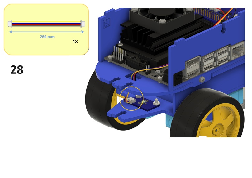
Step 28#
Substeps:
Connect a
260 mmJST cable to the connector on the IMU PCB as shown below.From the bottom side of the middle plate, feed the cable through the front slot in the middle plate as shown below.
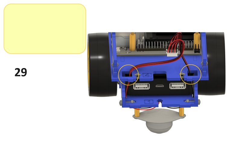
Step 29#
From the bottom side of the middle plate, feed the motor cables through the back side slots in the middle plate as shown below.
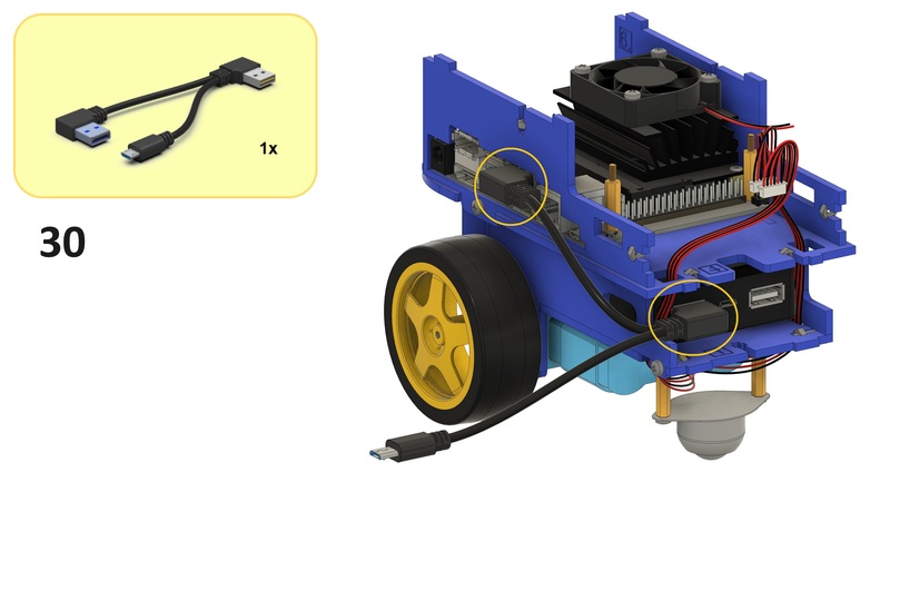
Step 30#
Substeps:
Connect the middle USB type A connector of the USB type A to USB type A and Micro USB cable to the left USB type A connector on the Duckiebattery as shown below.
Connect the other USB type A connector of the USB type A to USB type A and Micro USB cable to a USB type A connector on the Jetson Nano as shown below.
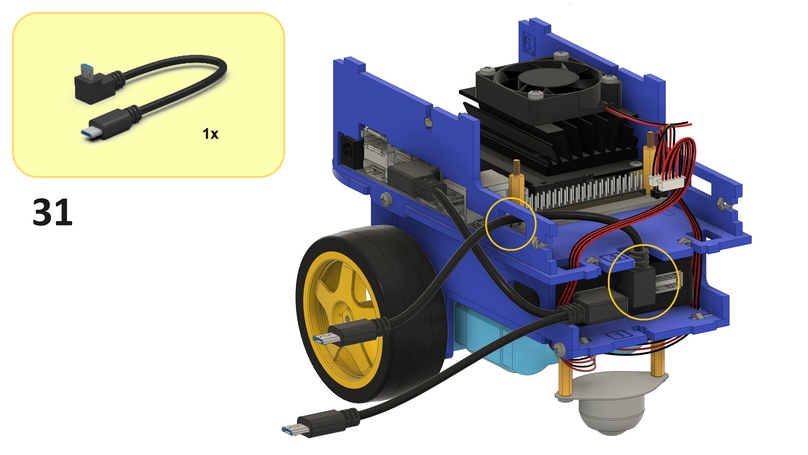
Step 31#
Substeps:
Connect the right-angled Micro USB connector of the Micro USB to Micro USB cable to the Micro USB connector on the Duckiebattery as shown below.
From the right side of the left top side plate, feed the cable through the back slot in the left top side plate as shown below.
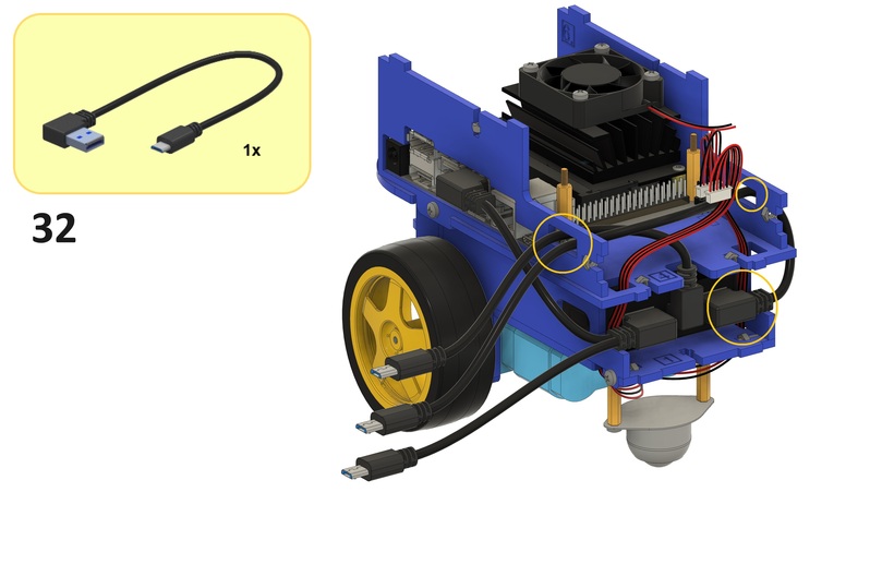
Step 32#
Substeps:
Connect the USB type A connector of the USB type A to Micro USB cable to the right USB type A connector on the Duckiebattery as shown below.
From the right side of the right top side plate, feed the cable through the back slot in the right top side plate as shown below.
From the right side of the left top side plate, feed the cable through the back slot in the left top side plate as shown below.
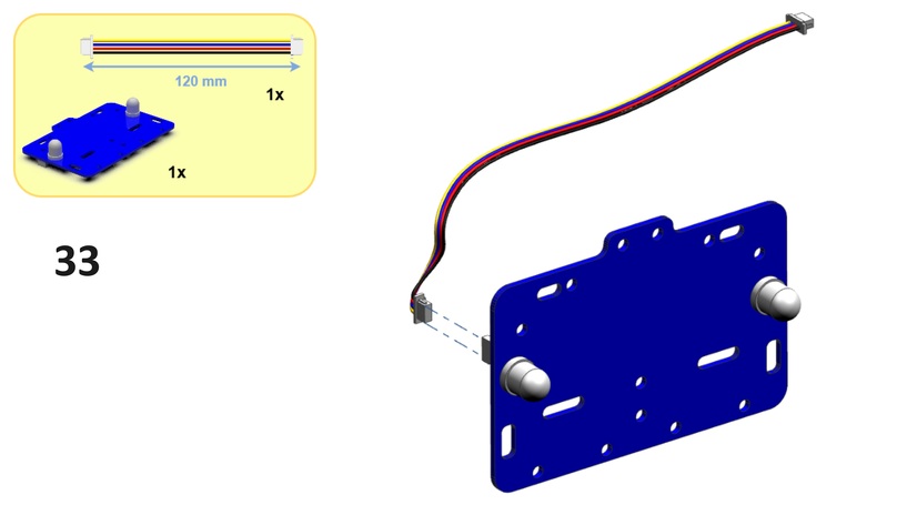
Step 33#
Connect a 120 mm JST cable to the connector on the back bumper as shown below.
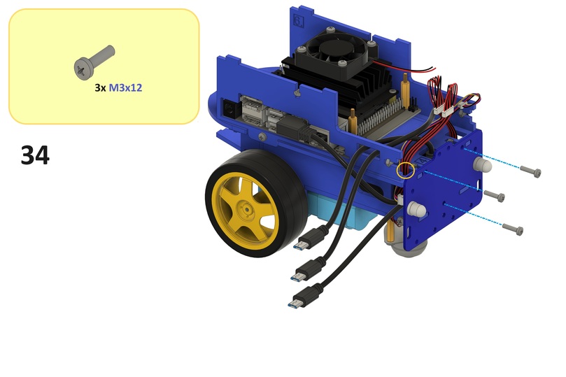
Step 34#
Substeps:
From the bottom side of the middle plate, feed the cable from Step 33 through the left back side slot in the middle plate as shown below.
Screw the back bumper onto the back sides of the bottom and middle plates using three
M3x12screws and threeM3nuts from Step 16 and Step 24 as shown below.
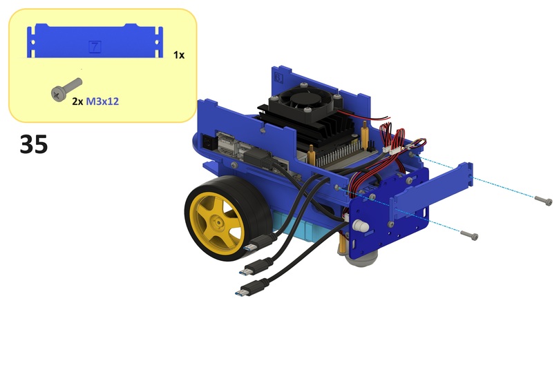
Step 35#
Screw the back plate onto the back side of the top side plates using two M3x12 screws and two M3 nuts from Step 25 and Step 26 as shown below.
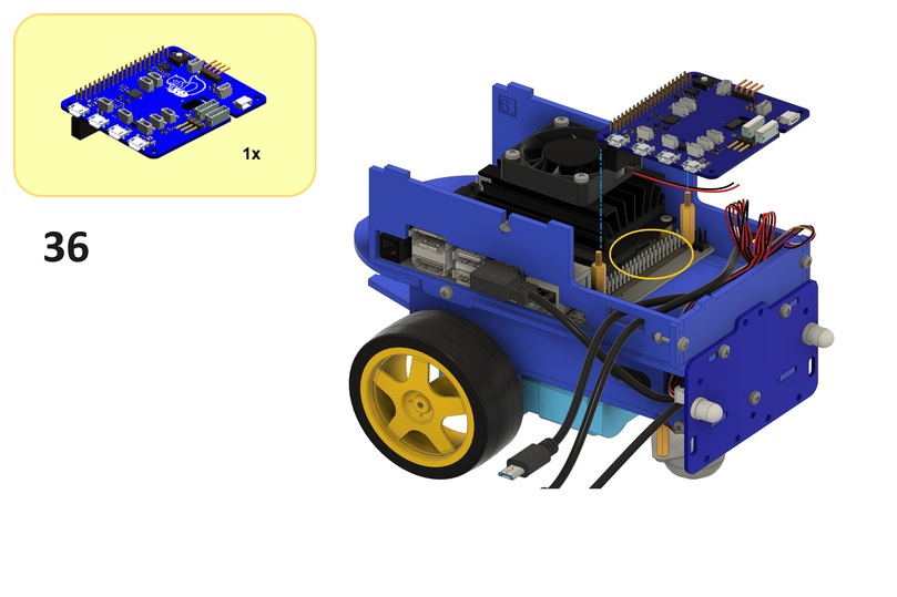
Step 36#
Leaving the motor cables and cable from Step 33 easily accessible (for Step 37, Step 38 and Step 39), connect the GPIO header on the HUT to the GPIO pins on the Jetson Nano such that each GPIO pin on the Jetson Nano is in contact with its respective contact in the GPIO header on the HUT as shown below.
Step 37#
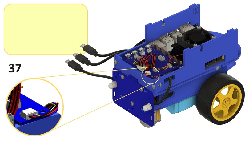
Connect the cable from Step 33 to the connector labeled LED-B on the HUT as shown below.
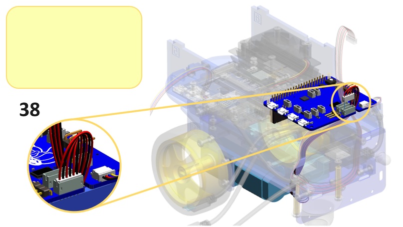
Step 38#
Substeps:
From the bottom of the HUT, feed the motor cables through the slot in the HUT as shown below.
Connect the left motor cable to the connector labeled
MOT-1on the HUT as shown below.
Step 39#
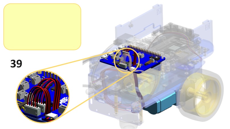
Connect the right motor cable to the connector labeled MOT-2 on the HUT as shown below.
Step 40#
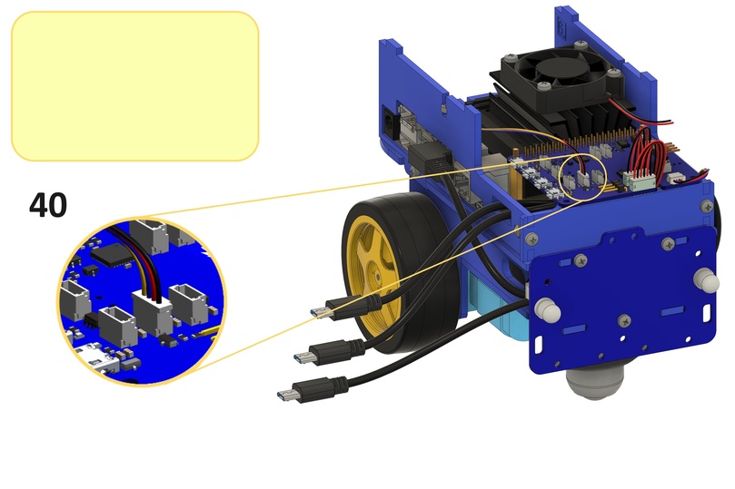
Connect the cable from Step 28 to the middle connector labeled I2C on the HUT as shown below.
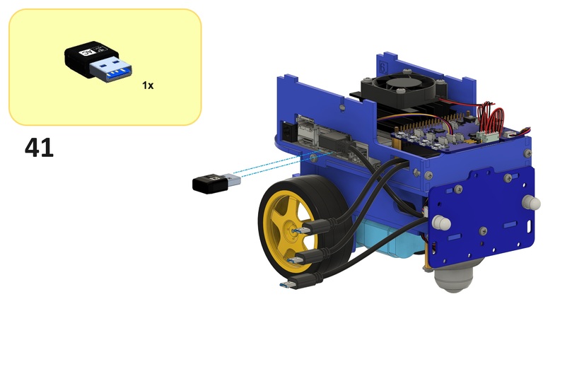
Step 41#
Connect the Wi-SFi dongle to a USB type A connector on the Jetson Nano as shown below.
Front assembly#
This section describes the steps to assemble the front assembly.
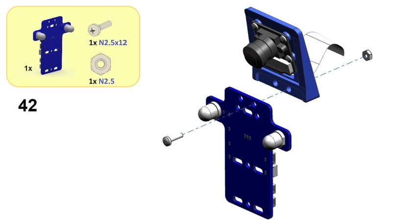
Step 42#
Screw the front bumper onto the front side of the camera holder using a N2.5x12 screw fed through the left screw hole of the camera holder and a N2.5 nut as shown below.
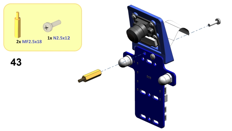
Step 43#
Screw an MF2.5x18 standoff onto the front side of the front bumper using an N2.5x12 screw fed through the right screw hole of the camera holder as shown below.
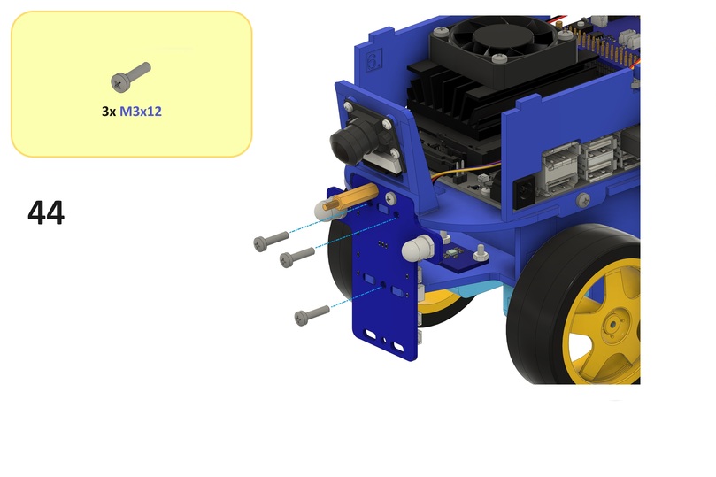
Step 44#
Note
Optionally, complete this step after Step 50.
Screw the front bumper onto the front sides of the bottom and middle plates using three M3x12 screws and three M3 nuts from Step 16 and Step 24 as shown below.
Step 45#
Substeps:
Gently open but do not remove the/a camera cable connector on the Jetson Nano as shown below.
Connect the camera cable to the camera cable connector on the Jetson Nano such that the pins on the camera cable come into contact with those in the camera cable connector on the Jetson Nano as shown below (the blue strip on the camera cable should face away from the Jetson Nano).
Close the camera cable connector on the Jetson Nano as shown below.
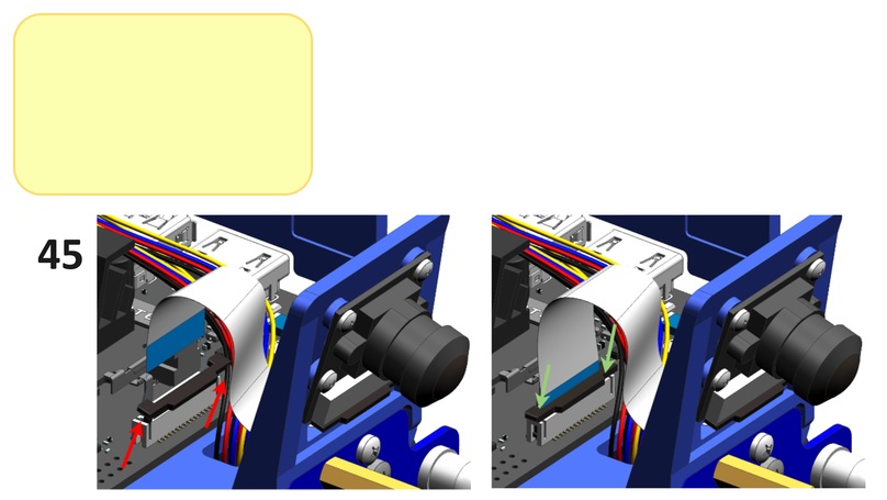
Note
This will create a twist in the camera cable.
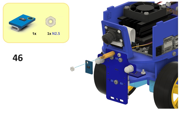
Step 46#
Screw the ToF sensor PCB onto the standoff from Step 43 using an N2.5 nut as shown below.
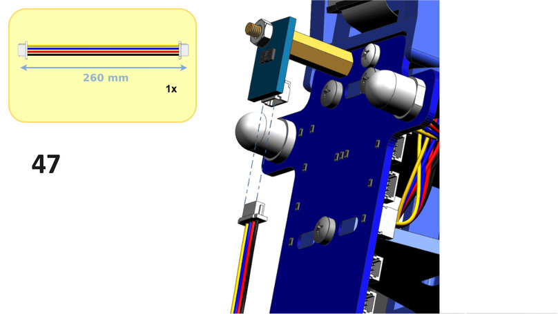
Step 47#
Connect a 260 mm JST cable to the connector on the ToF sensor PCB as shown below.
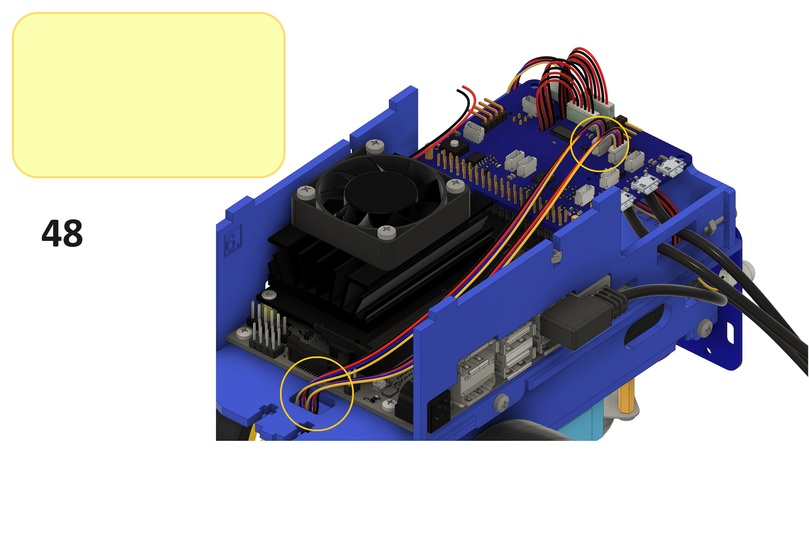
Step 48#
Substeps:
From the bottom side of the middle plate, feed the cable from Step 47 through the front slot in the middle plate as shown below.
Connect the cable to the right connector labeled
I2Con the HUT as shown below.
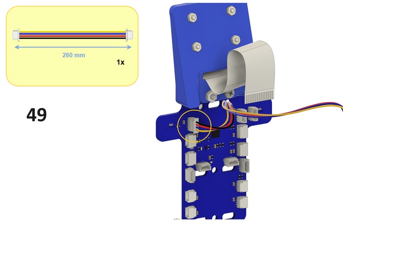
Step 49#
Connect a 260 mm JST cable to the connector labeled LED-F on the front bumper as shown below.
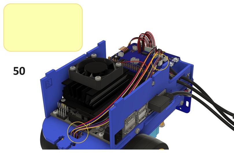
Step 50#
Substeps:
From the bottom side of the middle plate, feed the cable from Step 49 through the front slot in the middle plate as shown below.
Connect the cable to the connector labeled
LED-Fon the HUT as shown below.
Step 51#
This step has been removed.
Top assembly#
This section describes the steps to assemble the top assembly.
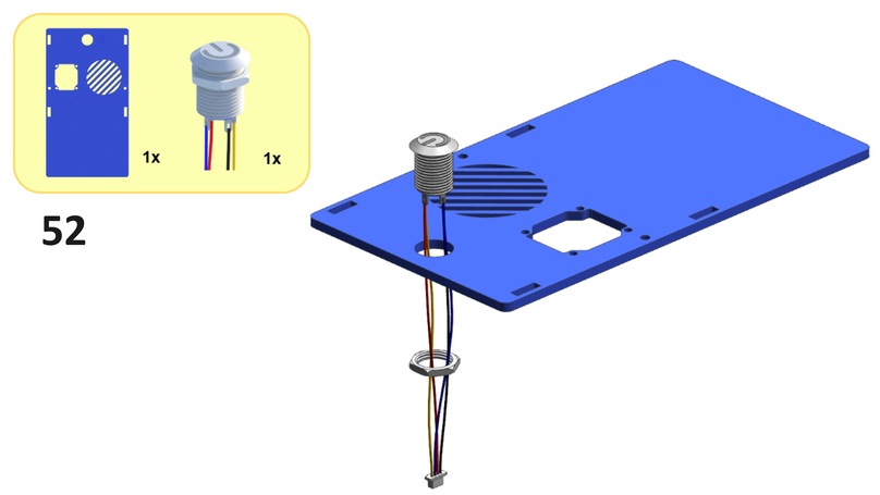
Step 52#
Substeps:
From the top side of the top plate, feed the top button cables through the top button hole in the top plate as shown below.
Screw the top button onto the top side of the top plate using the top button nut as shown below.
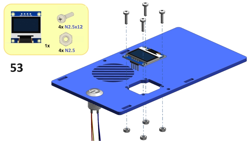
Step 53#
Screw the screen onto the top side of the top plate using four N2.5x12 screws and four N2.5 nuts as shown below.
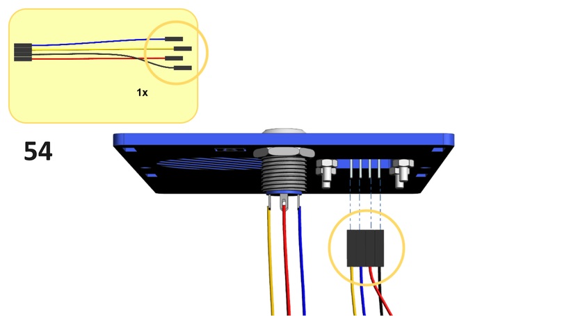
Step 54#
Substeps:
Connect the blue camera cable to the pin labeled
SDAon the screen as shown below.Connect the yellow camera cable to the pin labeled
SCLon the screen as shown below.Connect the black camera cable to the pin labeled
GNDon the screen as shown below.Connect the red camera cable to the pin labeled
VCCon the screen as shown below.
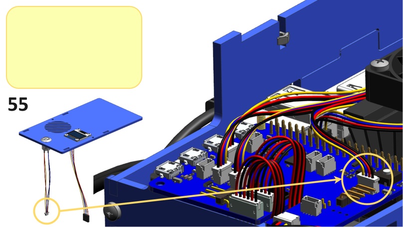
Step 55#
Connect the cable from Step 52 to the connector next to the button on the HUT as shown below.
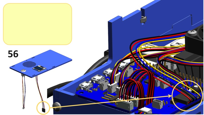
Step 56#
Substeps:
Connect the blue cable from Step 54 to the pin labeled
SDAon the HUT as shown below.Connect the yellow cable from Step 54 to the pin labeled
SCLon the HUT as shown below.Connect the black cable from Step 54 to the pin labeled
GNDon the HUT as shown below.Connect the red cable from Step 54 to the pin labeled
3.3Von the HUT as shown below.
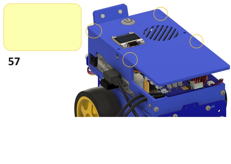
Step 57#
From the bottom side of the top plate, place the top side plates into the slots in the top plate as shown below.
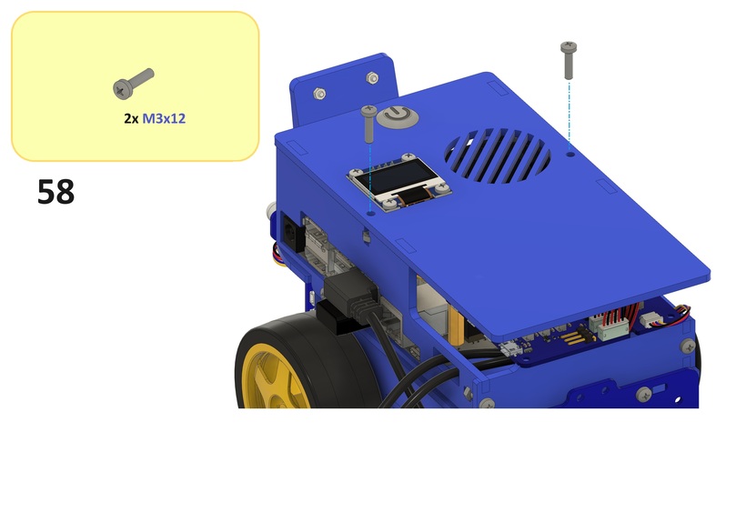
Step 58#
Screw the top plate onto the top sides of the top side plates using two M3x12 screws and two M3 nuts from Step 25 and Step 26 as shown below.
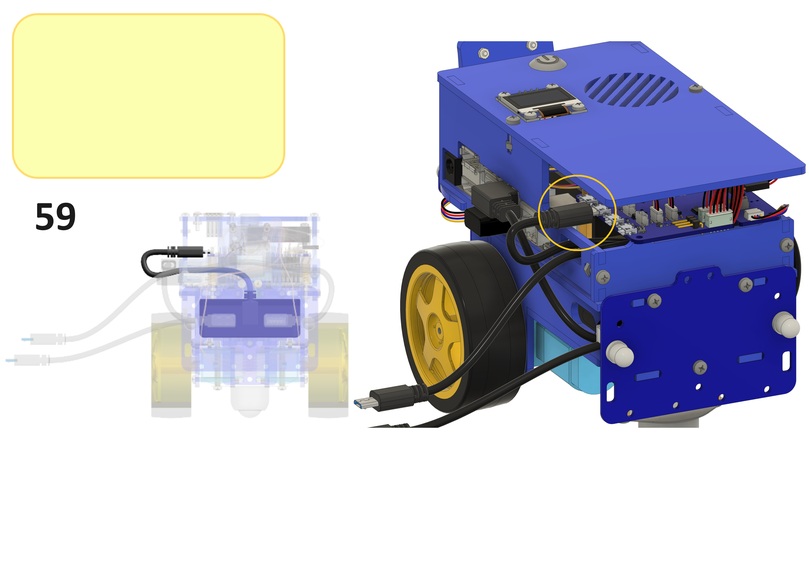
Step 59#
Connect the Micro USB connector of the Micro USB to Micro USB cable to the connector labeled CHARGER IN on the HUT as shown below.
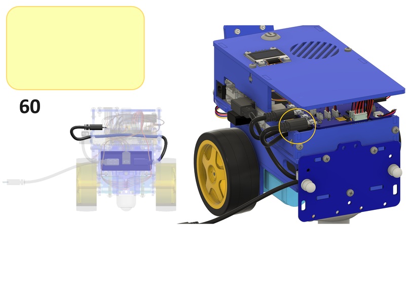
Step 60#
Connect the Micro USB connector of the USB type A to Micro USB cable to the connector labeled 5VEXT on the HUT as shown below.
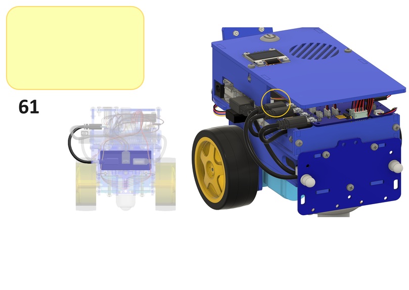
Step 61#
Connect the Micro USB connector of the USB type A to USB type A and Micro USB cable to the connector labeled 5VRASPI on the HUT as shown below.
Duckiebattery#
The connector labeled OUT CHARGER on the HUT will be used for charging the Duckiebattery.
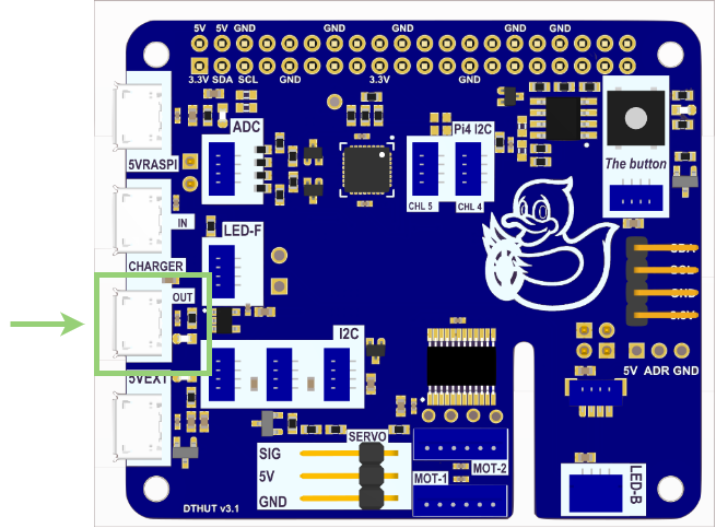
Note
For more information on how to charge the Duckiebattery, follow How to charge the Duckiebot.
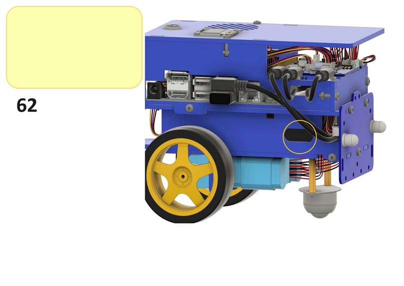
Step 62#
The button on the Duckiebattery can be accessed through the slot in the left bottom side plate as shown below.
SD card#
Insert the SD card into the Jetson Nano as shown below.
Optional components#
Back pattern assembly#
The back pattern enables the traffic management behavior used in demonstrations with other Duckiebots.
This section describes the steps to assemble the back pattern assembly.
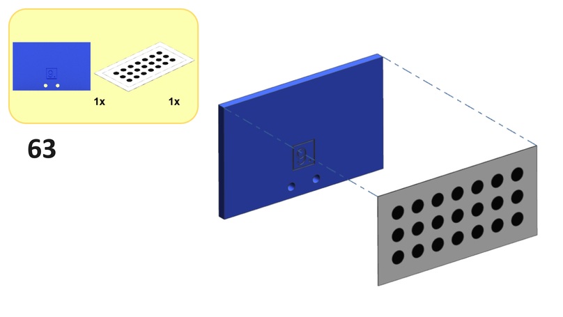
Step 63#
Place the back pattern onto the back side of the back pattern plate as shown below.
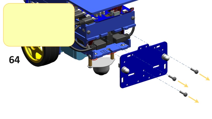
Step 64#
Unscrew the back bumper from the back sides of the bottom and middle plates as shown below.
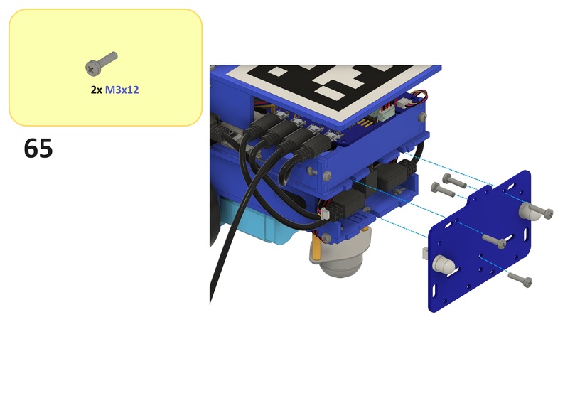
Step 65#
Substeps:
From the front side of the back bumper, feed two
M3x12screws through the top screw holes of the back bumper as shown below.Screw the back bumper back onto the back sides of the bottom and middle plates using three
M3x12screws and threeM3nuts from Step 16 and Step 24 as shown below.
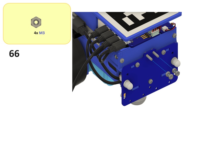
Step 66#
Substeps:
Screw two
M3nuts onto the back side of the back bumper using twoM3x12screws from Step 65 as shown below.Screw another
M3nut onto each of theM3nuts as shown below.
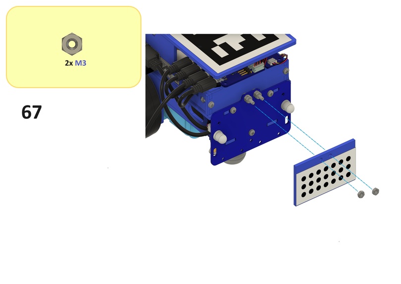
Step 67#
Screw the back pattern plate onto the M3 nuts from Step 66 using two M3 nuts as shown below.
AprilTag#
The top facing AprilTag enables localization in Duckietown Autolabs.
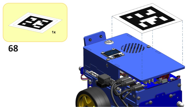
Step 68#
Place the AprilTag onto the top side of the top plate as shown below.
FCC-CE sticker#
Duckiebots are FCC and CE certified, meaning that they comply with (and surpass) material quality (e.g., RoHS 2.0) and electrical interference standards (FCC and CE).
Step 69#
Place the FCC-CE sticker somewhere on your Duckiebot as shown below.
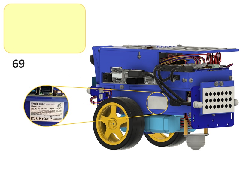
Tip
To prevent detection issues in more advanced applications with other Duckiebots, place the FCC-CE sticker in a location that is out of sight for those Duckiebots (e.g., under the wheels).
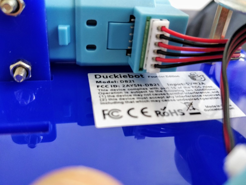
Fig. 16 An FCC-CE sticker placed under the wheels of a Duckiebot.#
Checkpoint#
Before proceeding, make sure that:
You have used every type of connecting component at least once, by referring to Fig. 2.
Every cable is plugged in correctly but try not use force on your Duckiebot, as it is (almost) never useful and may lead to undesirable outcomes.
The SD card is inserted into the dedicated SD card slot under the main board of the Jetson Nano (i.e., not in the adapter or in a USB connector).
Congratulations, your Duckiebot DB21J is now assembled!
Troubleshooting#
Troubleshooting
SYMPTOM
I can not find the blue chassis.
RESOLUTION
It may be under the white foam inside the Duckiebox. Try to remove the inner packaging to access it.
Troubleshooting
SYMPTOM
The Duckiebattery does not sit flush against the bottom plate.
RESOLUTION
Position the Duckiebattery to fit at an angle. While this may make the assembly a little trickier, everything will work out in the end.
Troubleshooting
SYMPTOM
I do not have enough screws of a specific type.
RESOLUTION
Every Duckiebox comes with enough screws of every type, plus spares for certain types. You may have inadvertently used the incorrect type of screw at certain points during the assembly.
Troubleshooting
SYMPTOM
I cannot screw the omni wheel in correctly, as the screws do not fit all the way into the standoffs.
RESOLUTION
Occasionally the standoffs are not fully threaded due to manufacturing inefficiencies. Try to orientate the stand-off such the shorter threaded side faces the chassis. Alternatively, try to use shorter screws (provided in the Duckiebox). Otherwise, try to use two spare nuts to mitigate tolerances, as shown below.
Troubleshooting
SYMPTOM
A component broke while I was trying to assemble my Duckiebot.
RESOLUTION
Certain components will not influence the functionality of your Duckiebot if broken. However, if a broken component is influencing the functionality of your Duckiebot and you cannot fix it yourself, take a picture of the damage and email hardware@duckietown.com.
Troubleshooting
SYMPTOM
The wheels wiggle and/or fall off the motors.
RESOLUTION
This may be due to manufacturing tolerances. Try to remove the distance disks between the motors and wheels, making sure that the wheels are not touching the screws of the motor mounts. Alternatively, screws are provided to fix the wheels to the motor axles, as shown below. Make sure not to tighten the screws too hard, as this may add resistance to the spinning of the wheels (you can find the sweet spot by turning the wheel by hand and feeling the resistive torque).
Troubleshooting
SYMPTOM
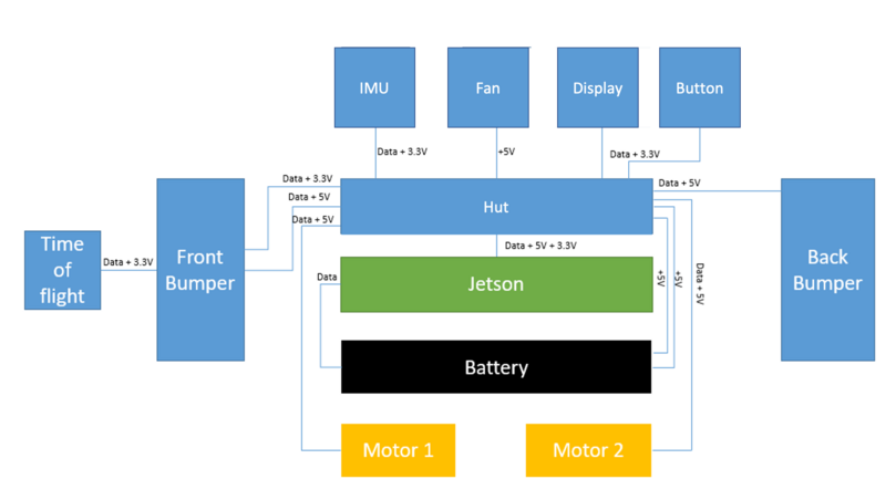
I do not understand my Duckiebot’s data and electrical connections.
RESOLUTION
A simplified block diagram of the data and electrical connections for your Duckiebot is shown below.
Troubleshooting
SYMPTOM
I have followed these instructions to the letter but there is something off that I cannot quite put my finger on.
RESOLUTION
You may have forgotten to put a duckie on top of your Duckiebot!