Assembly - Duckiebot DB21J
Contents
Assembly - Duckiebot DB21J#
What you will need
Duckiebot
DB21parts (get aDB21-Jx). If you are unsure what version of Duckiebot you have, check the overview of existing Duckiebot configurations.A micro SD card with the Duckiebot image on it. The procedure to flash the SD card is explained here.
3-4 hours of assembly time.
What you will get
An assembled Duckiebot in configuration
DB21J.
Foreword#
These instructions are your friend. Follow them carefully, especially if it is the first time you assemble a Duckiebot. Small variations might cause big effects (e.g., don’t flip your cables!).
Overview#
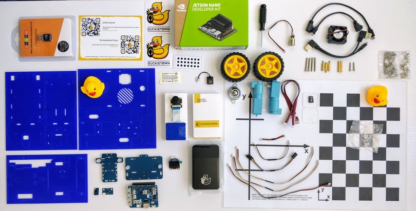
A Duckiebox contains the following components:
The assembly process is divided in 6 parts. They must be completed in the following order:
The Troubleshooting section at the bottom of this page provides resolutions to common problems.
Preliminary Steps#
Unboxing#
Unbox all of your components and lay them out on a flat surface. Ensure that you have well-lit, uncluttered space to work on.
Note
“The Duckiebox hides but does not steal”. Your Duckiebot chassis might be under the white protection foam inside the box. To reach it, pull out the white foam from the box after removing everything. Mind that the upper part of the inside foam has several side pockets in addition to a main compartment where components are located.
Although not necessary, a small (M2.5) wrench and pliers might ease some passages.
Note
Both NVIDIA Jetson Nano 2 GB and 4 GB are supported, but the SD cards must be initialized differently, as described in Setup - Duckiebot SD Card.
Plastic cover#
Peel the plastic cover from all the chassis parts, on both sides.
Screws, Nuts and Stand-offs#
Verify each connecting part before using them. This will prevent undesirable effects (e.g., nylon screws prevent electrical shorts; bigger screws might damage the chassis).
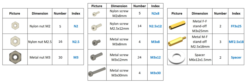
In addition, there are also shorter screws, which can be used in some cases.
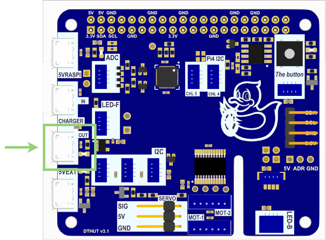
HUT#
Hut is the electronics board:
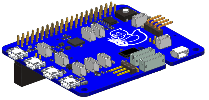
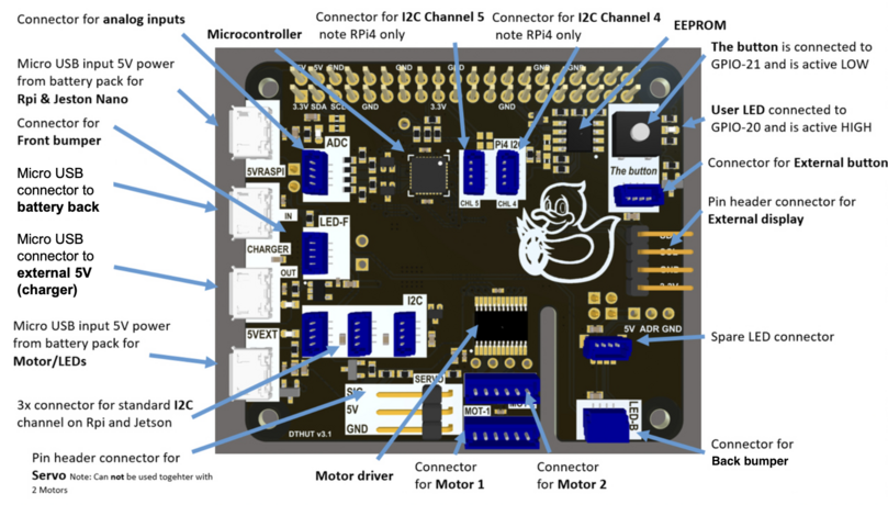
It contains the connectors for various sensors, the fan, motors, external button, etc. Also it is mounted to the NVIDIA Jetson Nano. A more detailed scheme is shown in the figure:
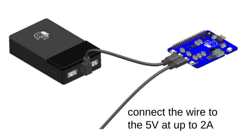
Charge Duckiebattery via the HUT#
This preliminary step allows us to start charging the battery while confirming the functionality of the HUT.
Connect the battery and the
HUTboard as shown and make sure a green LED on theHUTis lit.Wait 30 minutes and then push the button on the battery.
Check that the state of charge LEDs on the battery start blinking.
Leave this setup until the battery is charged. This may take up to 5 hours.
You can familiarize with how the Duckiebattery works by reading its handling instructions.
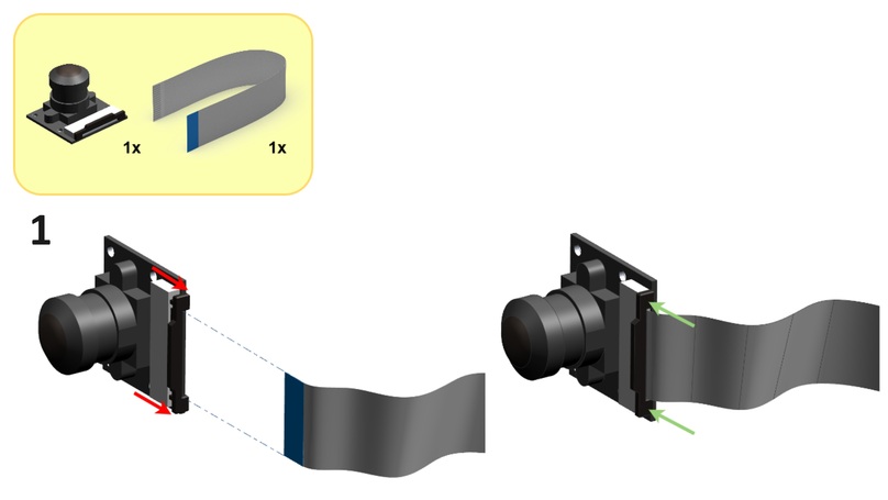
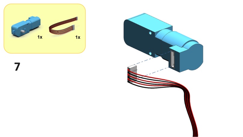
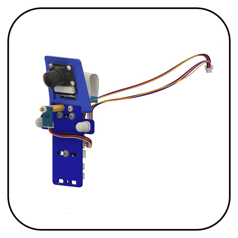
Camera Assembly#
This section (steps 1 to 2) guides you through the assembly of the camera assembly.
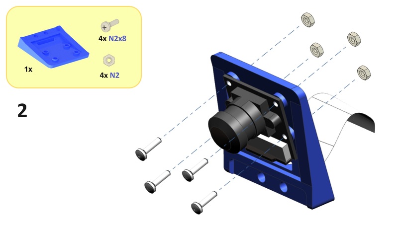
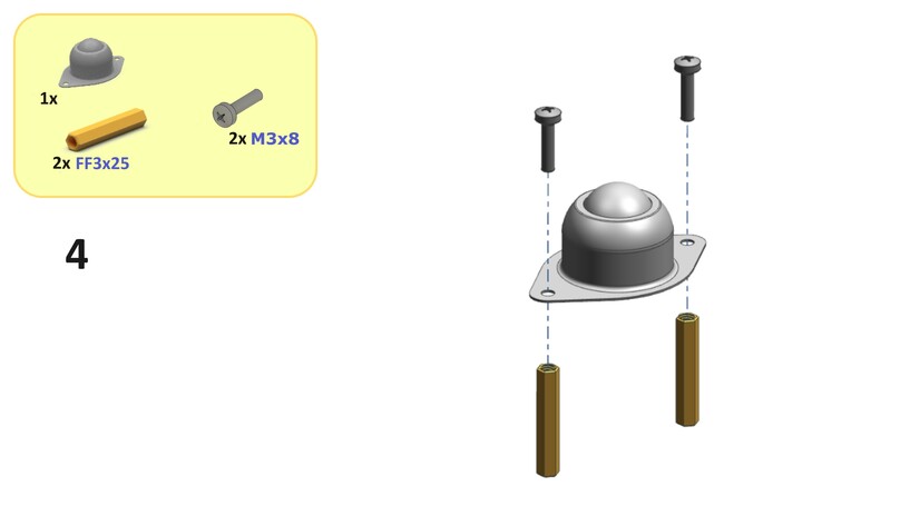
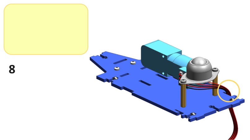
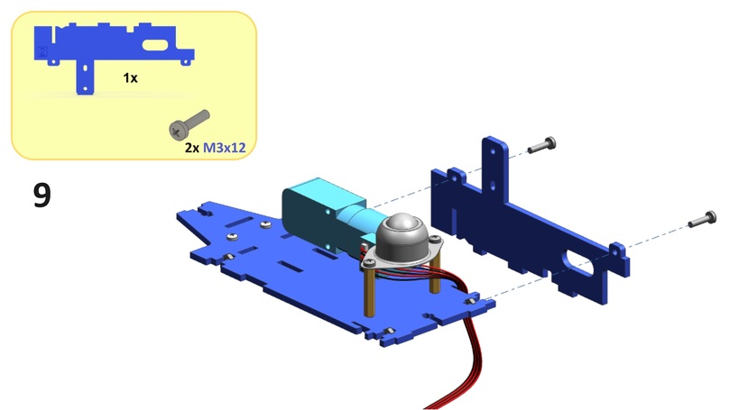
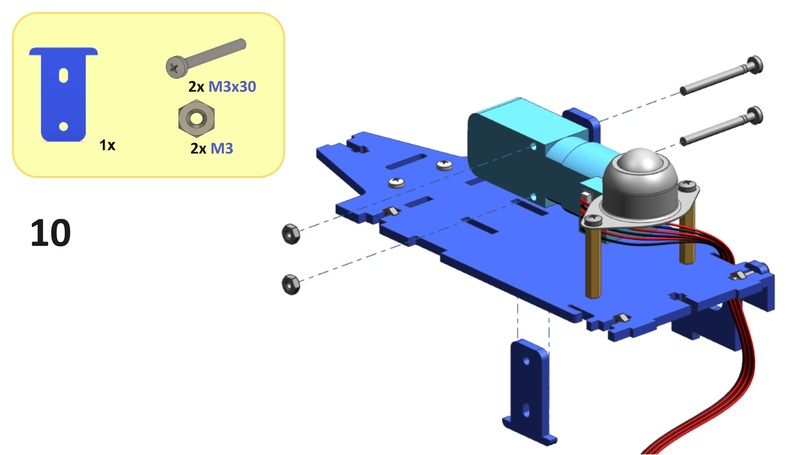
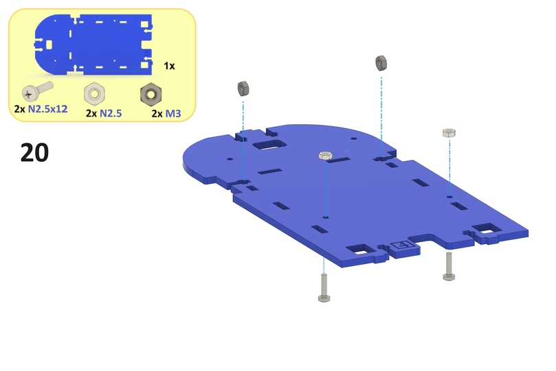
Base-plate#
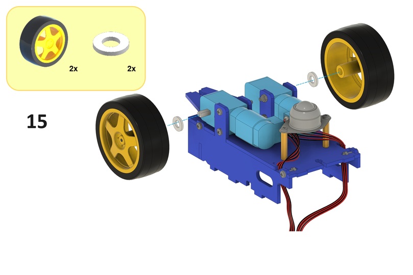
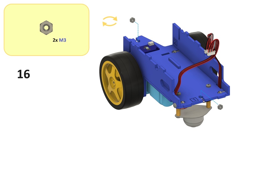
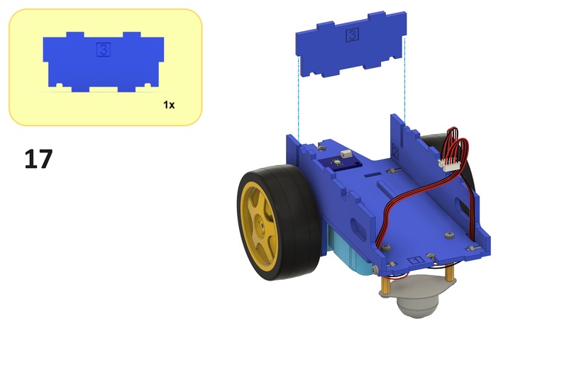
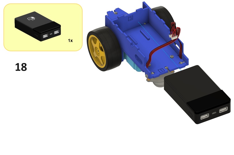
This section (steps 3 to 18) guides you through the assembly of the base-plate.
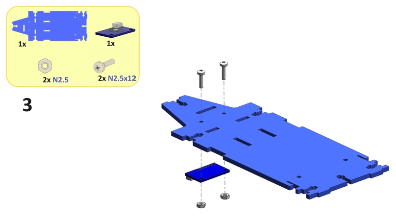
Note
For steps 4 and 5, try using shorter screws if the suggested screws do not fully insert into the standoffs.
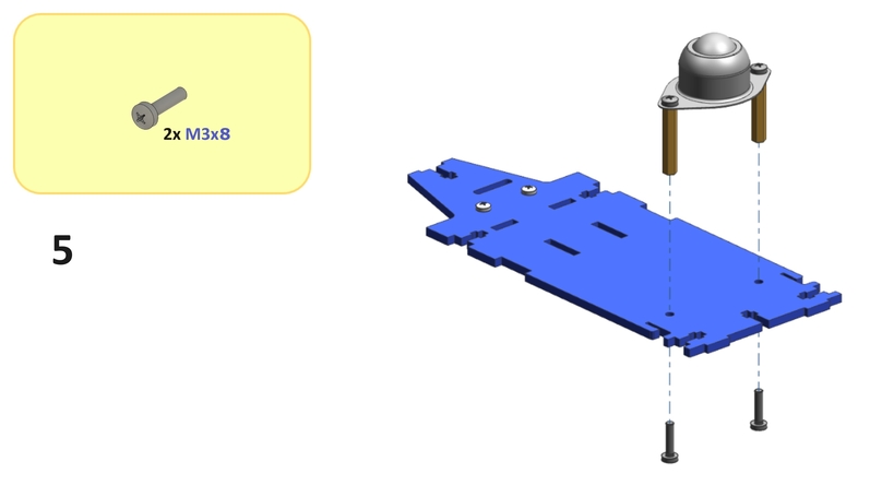
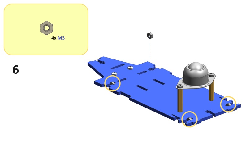
Note
Occasionally manufacturing tolerances (on the nut and the chassis) might prevent a flush fit. Trying a different nut or changing its orientation might solve the problem. Sometimes it may be convenient to use pliers.
Remove the USB cable from the Duckiebattery, connected in the battery related preliminary step.
Before proceeding, verify that no component is wiggling. The only things moving should be the cables and the sphere in the omni-wheel (and, yes, the motor axles). Proceed to gently tighten the screws of the offending parts, if necessary.
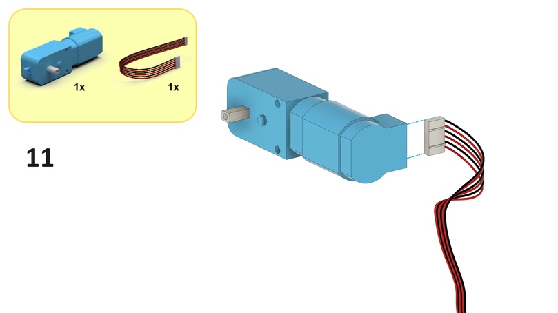
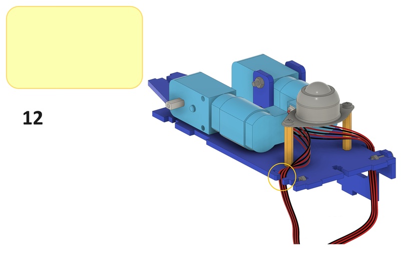
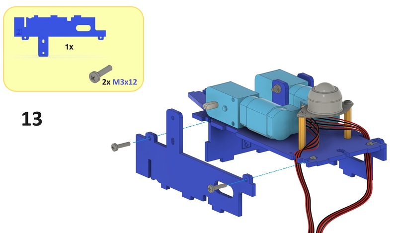
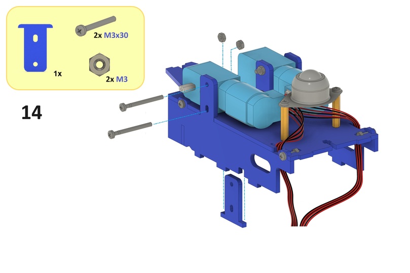
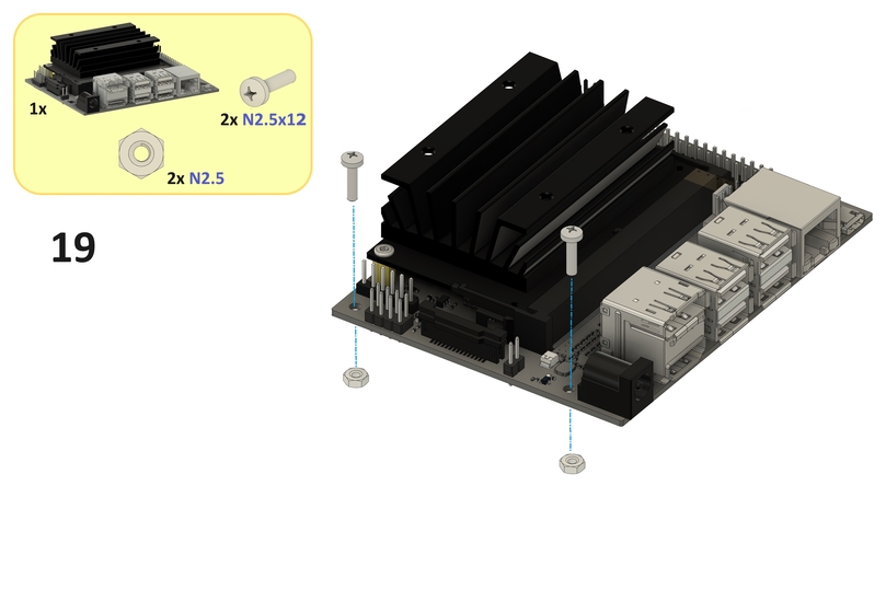
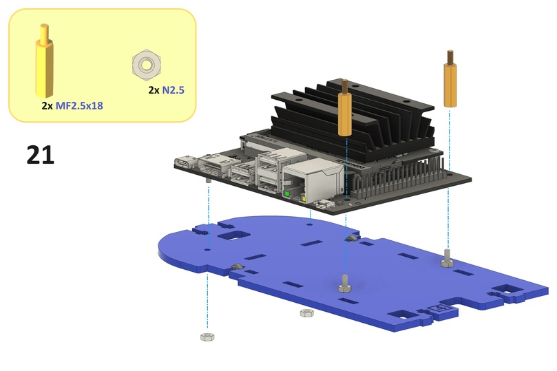
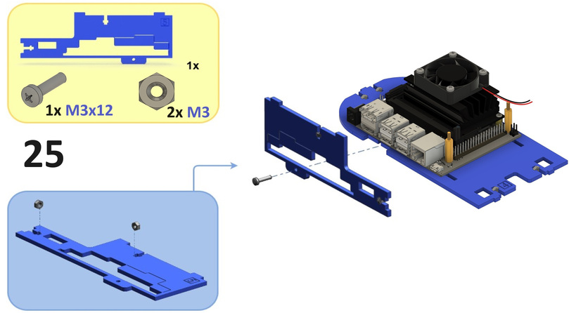
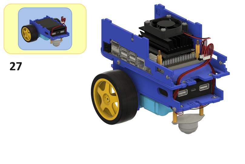
Computation Unit#
This section (steps 19 to 27) guides you through the assembly of the computation unit.
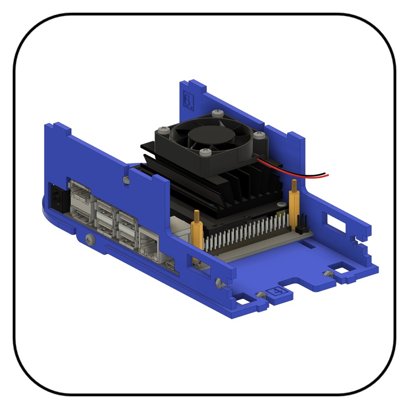
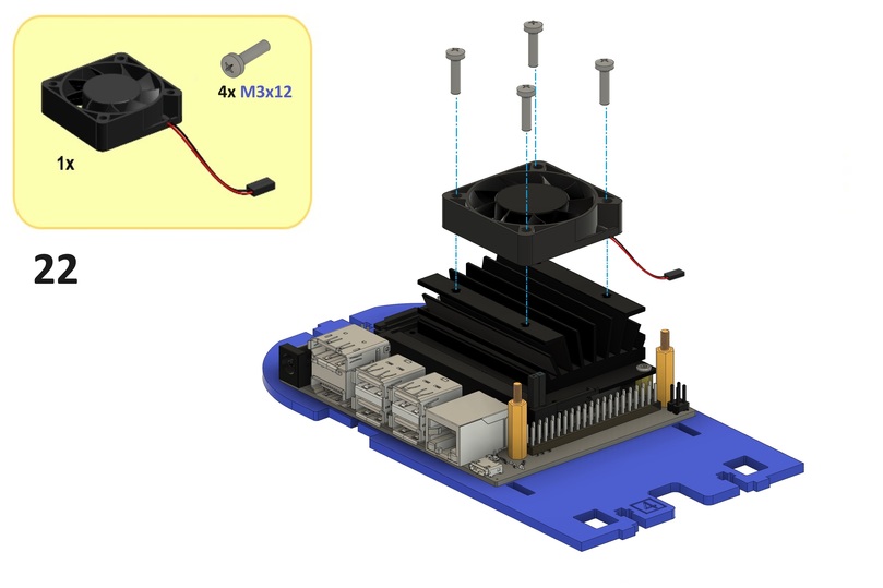
Note
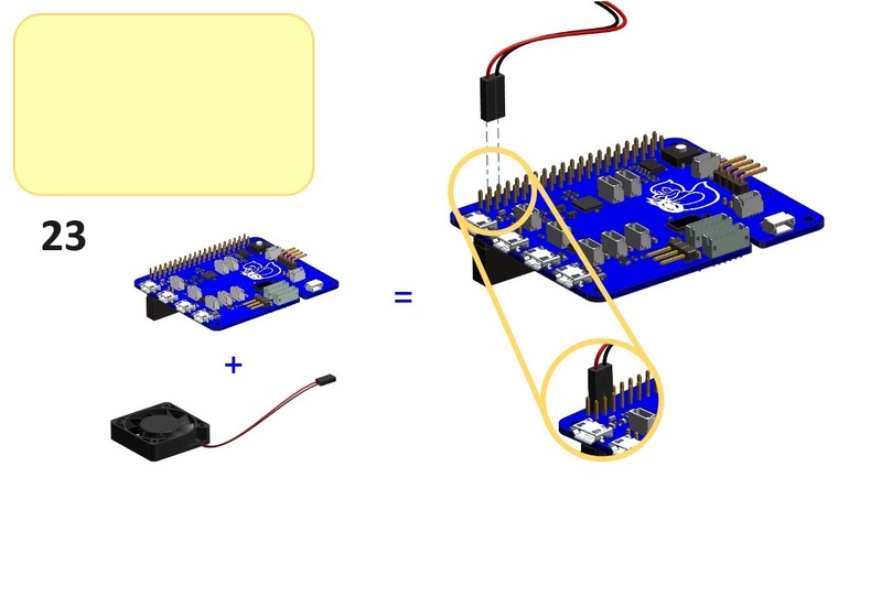
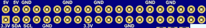
Connect the red fan cable to the 5V pin, as shown in step 23, or the 3.3V pin for a lower fan speed and less noise.
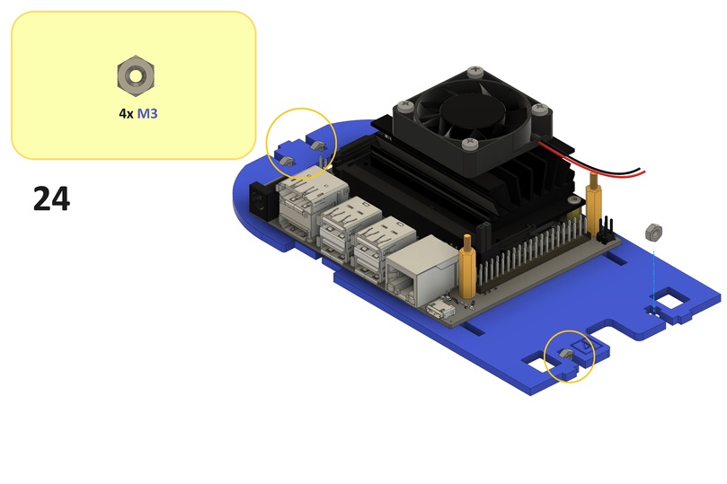
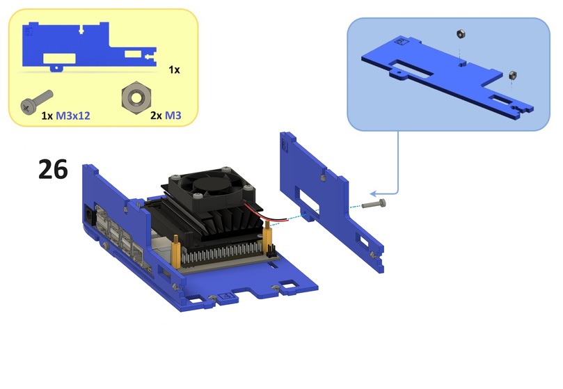
Now connect it to the base-plate (i.e, the rest of the chassis assembled in steps 3 to 18). Verify the chassis components are locked correctly.
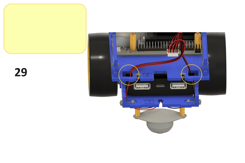
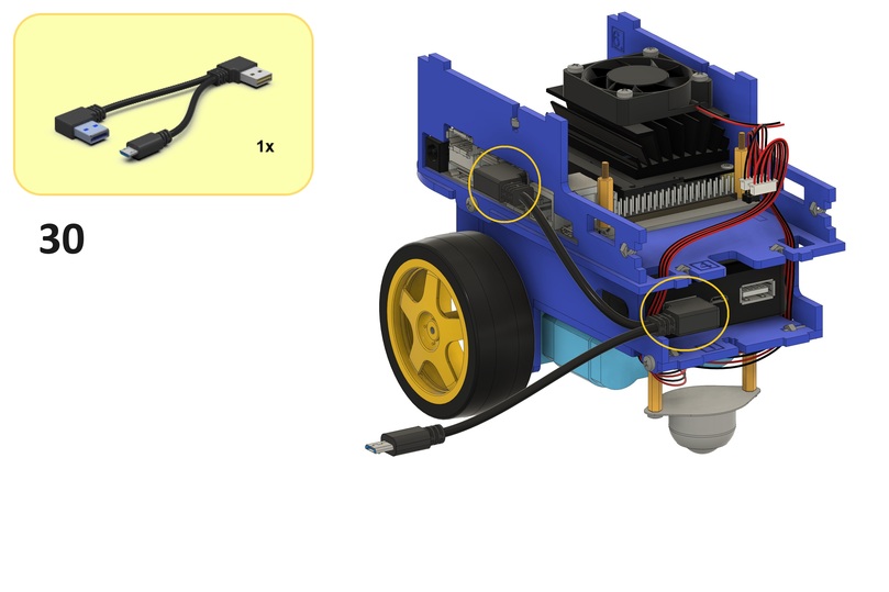
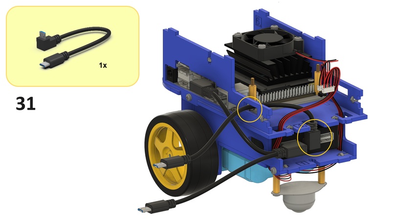
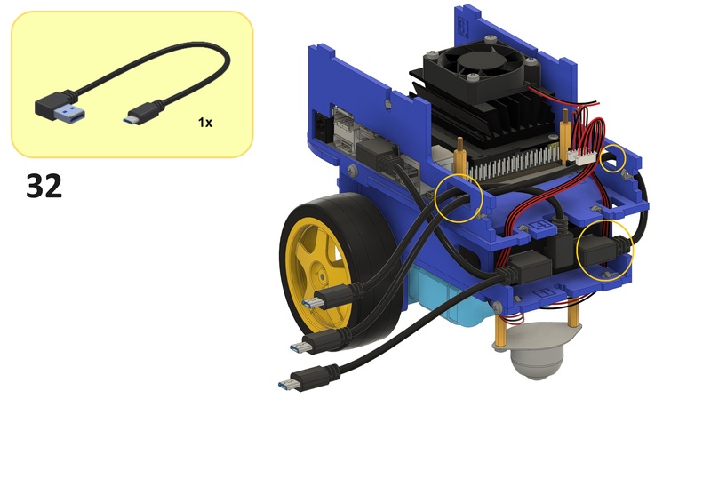
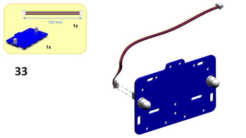
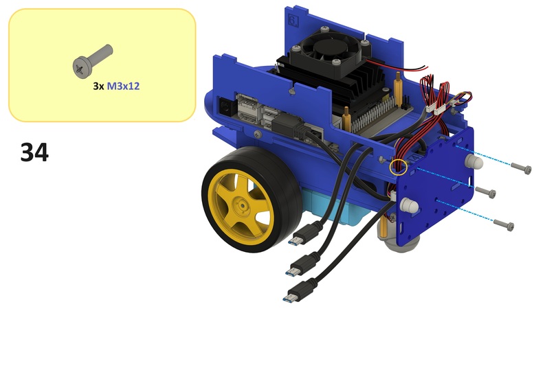
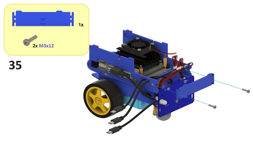
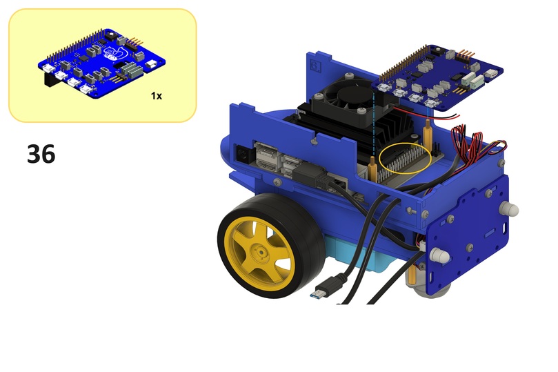
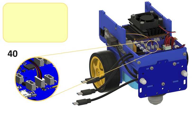
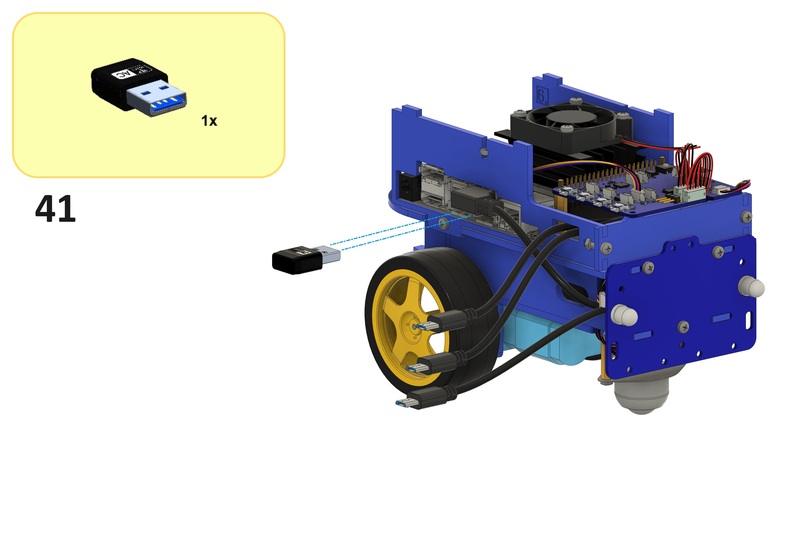
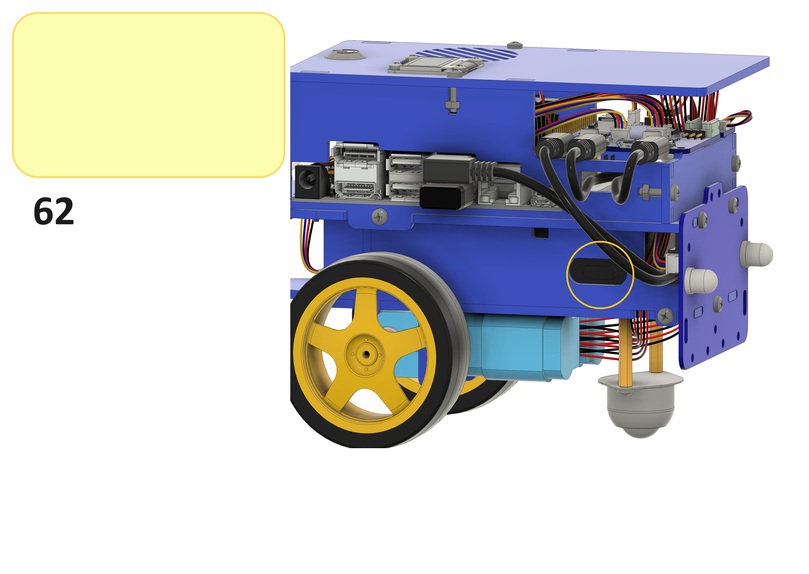
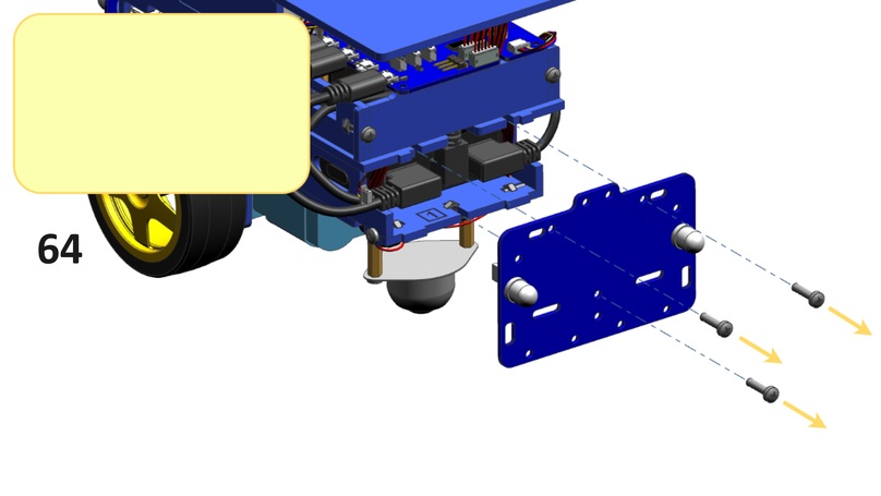
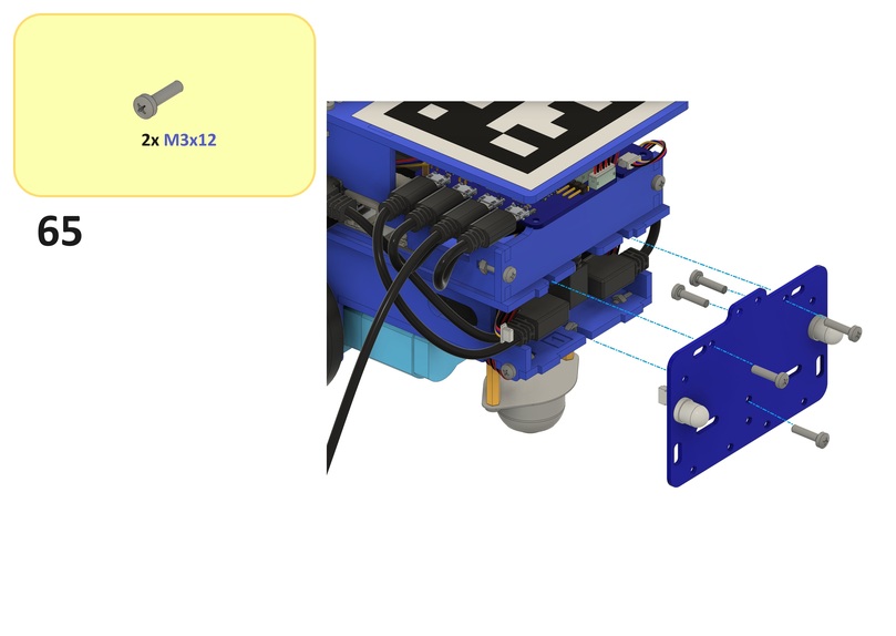
Rear Assembly#
This section (steps 28 to 41) guides you through the assembly of the rear assembly.
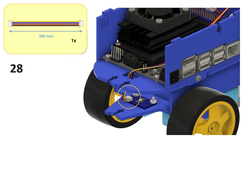
Note
Make sure that both rows of pins on the 40-pin expansion header on the Jetson Nano are connected to the corresponding contacts of HUT.
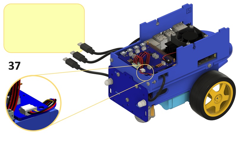
Note
The above refers to the IMU cable from step 28.
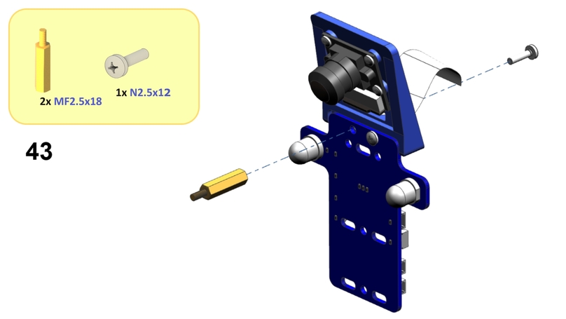
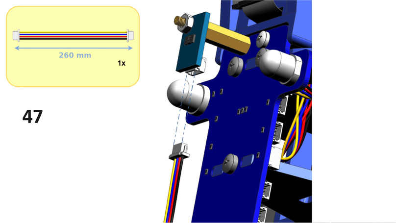
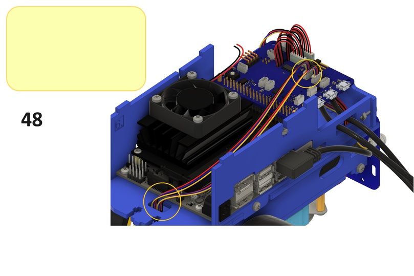
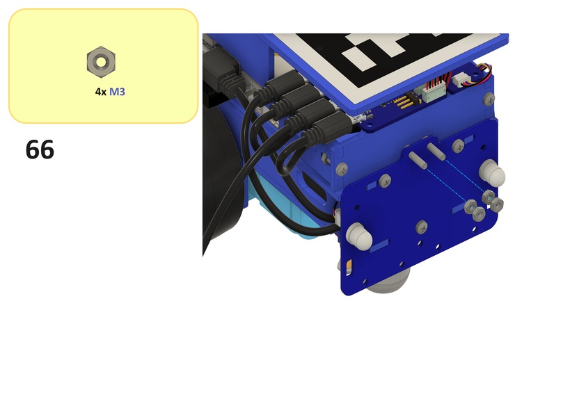
Front Assembly#
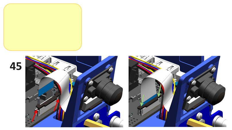
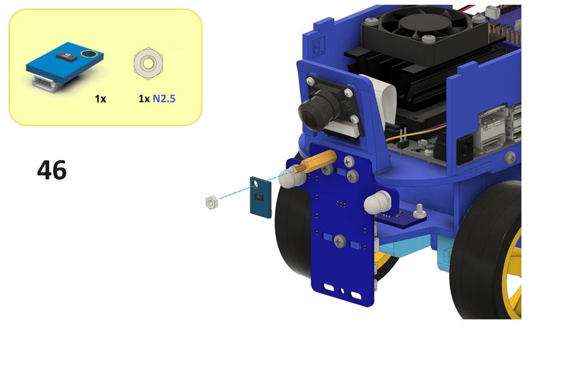
This section (steps 42 to 51) guides you through the assembly of the front assembly.
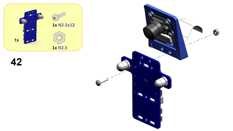
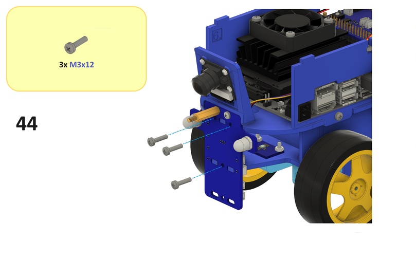
Note
Optionally, complete step 44 after step 50.
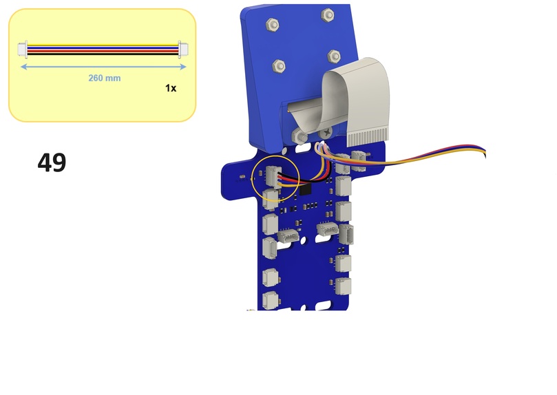
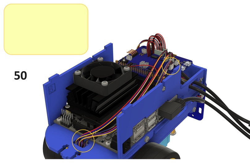
Note
Step 51 has been skipped.
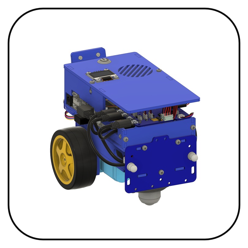
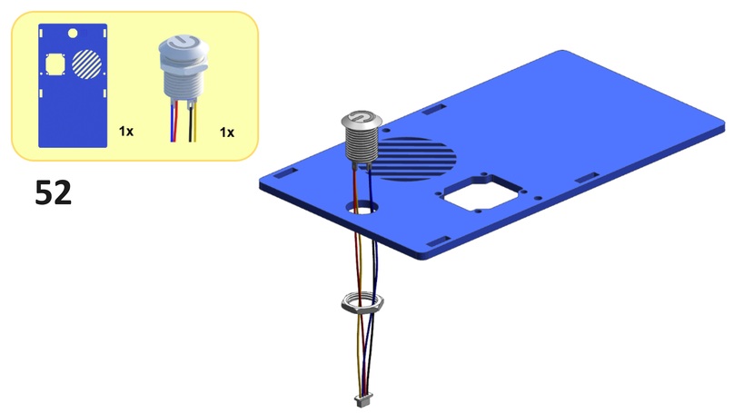
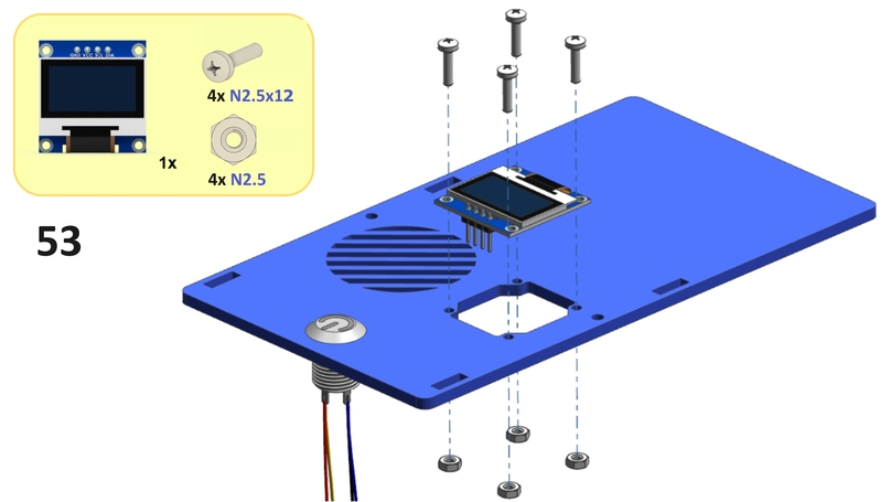
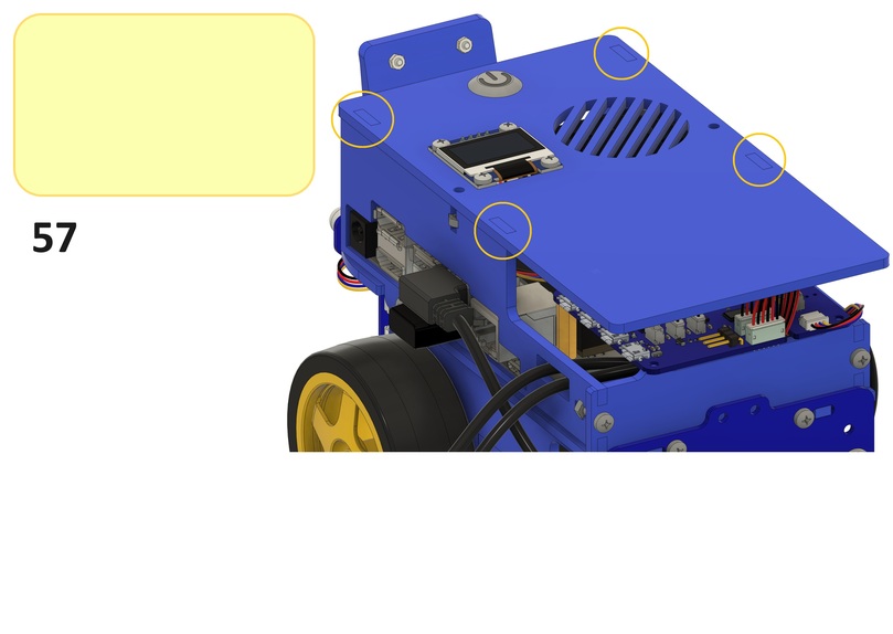
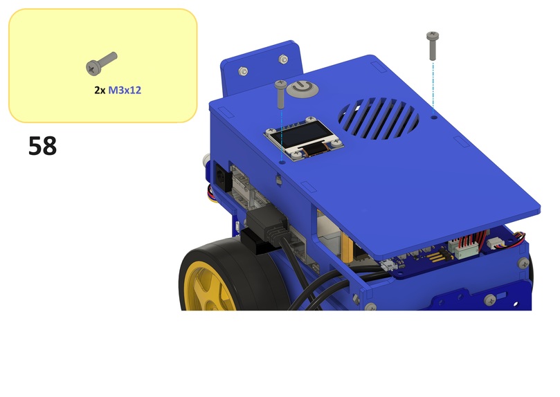
Top Deck Assembly#
This last section (steps 52 to 61) guides you through the assembly of the top deck assembly.
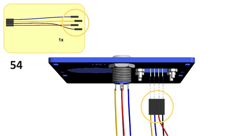
Attention
Make sure the cable connections between HUT and screen are as follows:
Blue cable:
SDA↔SDAYellow cable:
SCL↔SCLBlack cable:
GND↔GNDRed cable:
3.3V↔VCC
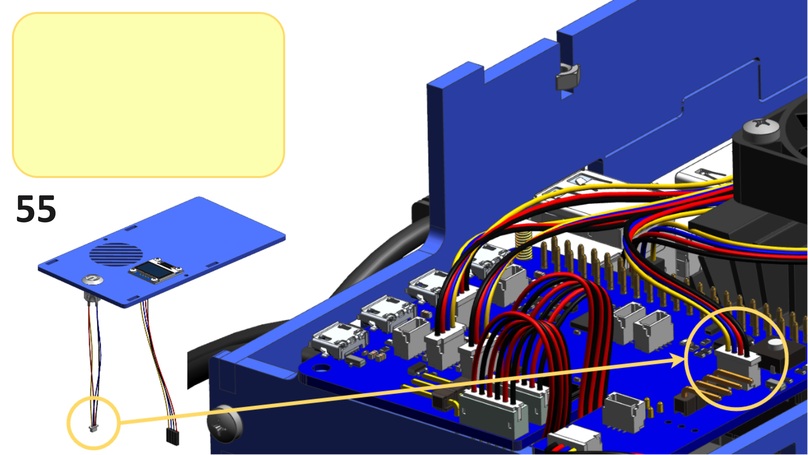
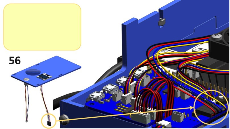
Note
On the display board you will see 4 pins: SDA, SCL, VCC, GND. Make sure that the correct color wire is connected to the corresponding pin on the HUT.
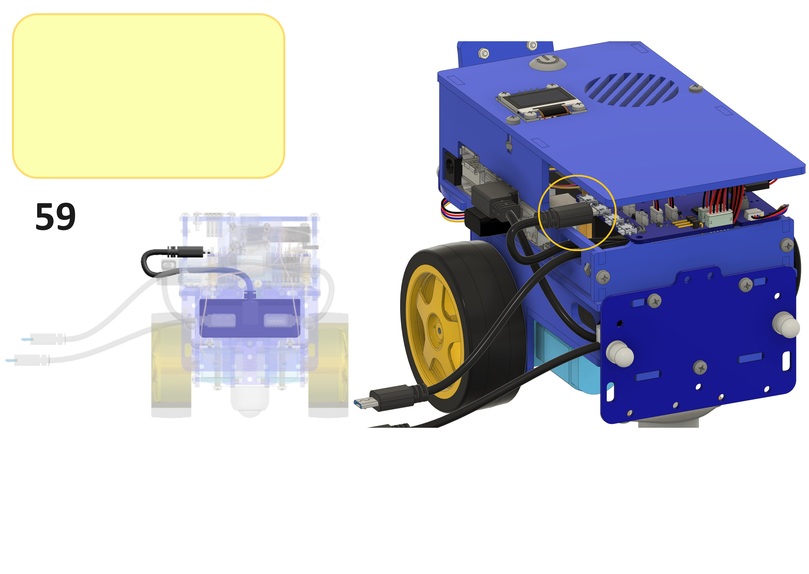
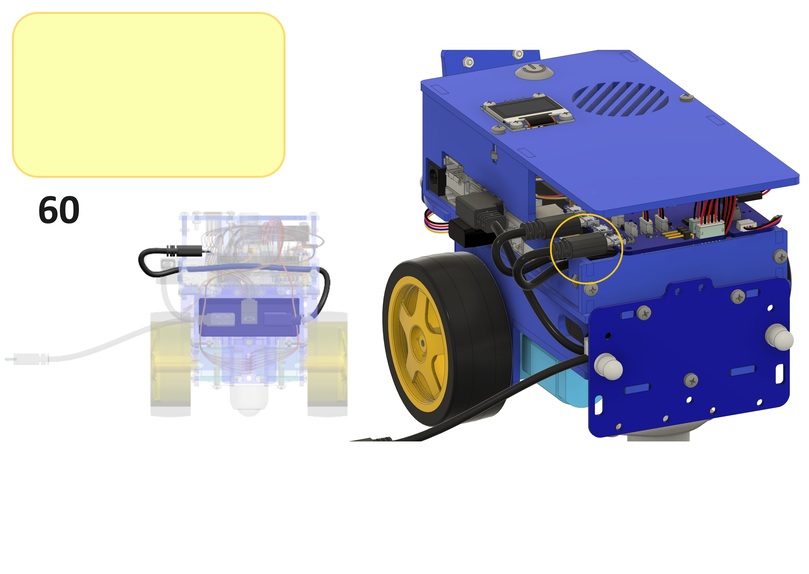
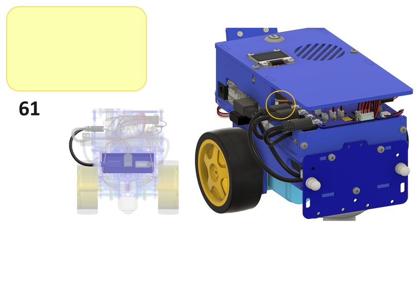
Power your Duckiebot#
One of the USB ports on the HUT will remain free. You can use this port to charge the Duckiebot. To avoid putting additional stress on the connector, you can leave this cable plugged in and store it under the blue top lid.
Warning
Always plug and unplug USB cables from the HUT with care!
Make sure the SD card was flashed successfully without any error during the process and it is plugged in Jetson Nano under the main board. ONLY then you can continue to follow the instructions. Once your Duckiebot is fully charged, you can press the button of the battery on the side to power it up. It is important to make sure the battery is charged to prevent undesired shutdown during the first boot, which will compromise the initialization sequence and require the sd card to be re-flashed.
Congratulations, your Duckiebot DB21J is now completely assembled.
Additional Parts#
These additional parts are not always necessary.
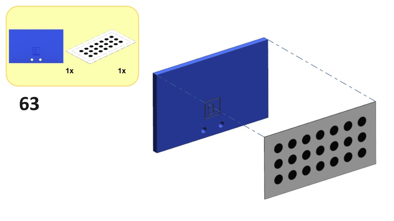
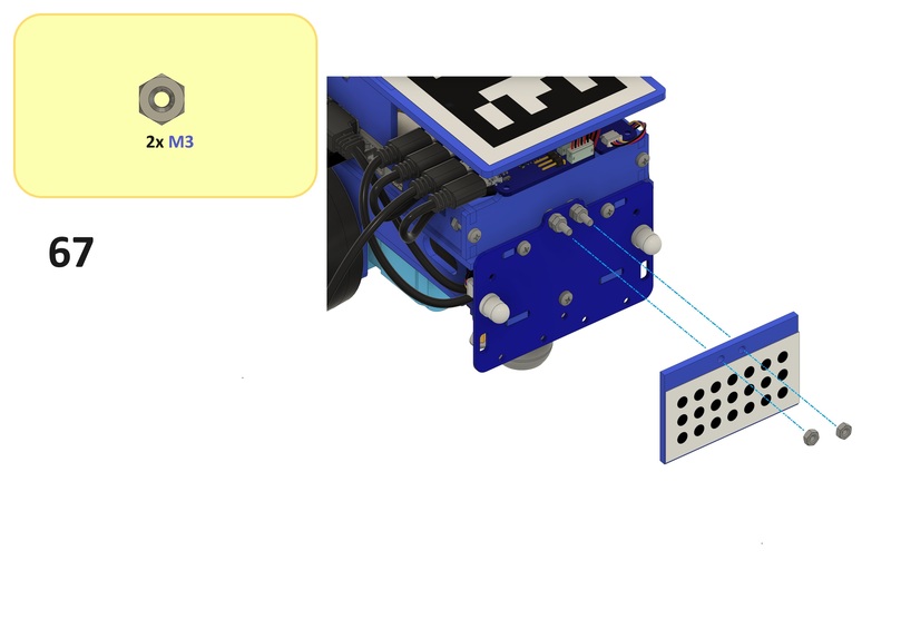
Back Pattern#
The back pattern enables the traffic management behavior used in challenges with vehicles (e.g., LFV, LFIV, etc.).
April Tag#
This top facing April Tag enables localization in Duckietown Autolabs.
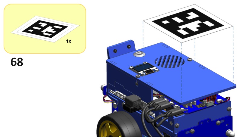
Note
Please place the sticker somewhere on the Duckiebot.
Check the outcome#
Look at the Overview of interlocking parts and make sure you have used each type at least once.
Check all cable connectors and make sure they are plugged in completely. Do not use force on the Duckiebot, it is (almost) never useful, and it might lead to undesirable outcomes.
Make sure you have flashed your SD card with the latest version of the Duckiebot image (configuration
DB21Mif using a Jetson Nano 2 GB,DB21Jif using a Jetson Nano 4 GB).Note
Version 1.2.2 is the minimum requirement for enabling battery code updates. Make sure you have at least this version (>22 March 2021).
Make sure the SD card is inserted in Jetson Nano in the dedicated SD card slot under the main board. Do not plug it in the adapter and in a USB port. If you have already inserted a flashed SD card, you are allowed to push the magic button on the battery.
Which LEDs you should see:
Blue LEDs when the robot is off and you plug in the charger (after it’s off);
White LEDs when the robot is on;
Random color LEDs when the robot is powering on.
Troubleshooting#
Troubleshooting
SYMPTOM
I can’t find the blue chassis.
RESOLUTION
It’s under the white foam in the Duckiebox. Remove the inner packaging to access it.
Troubleshooting
SYMPTOM
Camera cable needs to be twisted to make the pins on the cable matching those in the connector. Is this normal?
RESOLUTION
Yes this is normal. It might look a little nicer if you wire the camera cable around the metal stand-off next to the plug.
Troubleshooting
SYMPTOM
The Duckiebattery does not fit flush in the compartment.
RESOLUTION
Position it as it fits (at an angle). It will make the assembly a little trickier but everything will work out in the end.
Troubleshooting
SYMPTOM
I don’t have enough screws of a specific type.
RESOLUTION
Each package has enough screws of each type, plus spares of some. It might happen to inadvertently use one type instead of the correct one, which will result in shortages towards the final stages. Following the instructions carefully will prevent this from happening.
Troubleshooting
SYMPTOM
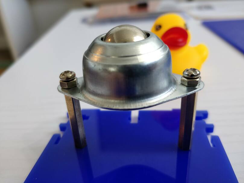
I can’t screw the omni-directional wheel right; the screws don’t fit all the way in the standoffs.
RESOLUTION
Occasionally the standoffs are not fully threaded due to manufacturing inefficiencies. The solution is to orient, in case of need, the shorter threaded stand-off side towards above, on the side of the chassis. Alternatively, shorter screws (provided in the package) can be used. If everything else fails, a “dirty” but effective solution is to use two spare nuts to mitigate tolerances, as shown in the picture below:
Troubleshooting
SYMPTOM
A piece broke while I was trying to assemble it!
RESOLUTION
Mistakes happen. Some damages will not influence the functionality of the robot, others will be fixable at home with some tools, others could be showstoppers. Please take a picture of the damage and email hardware@duckietown.com for assistance.
Troubleshooting
SYMPTOM
The wheels wiggle and/or fall off the motors.
RESOLUTION
This is due to manufacturing tolerances. You may remove the distance disks used in the assembly between motors and wheels, but make sure the wheels are not touching the screws of the motor mounts. Alternatively, screws are provided to fix the wheels to the motor axles. Make sure not to tighten the screws too hard, or they will add resistance to the spinning of the wheels (you can find the sweet spot by turning the wheel by hand and feeling the resistance torque).
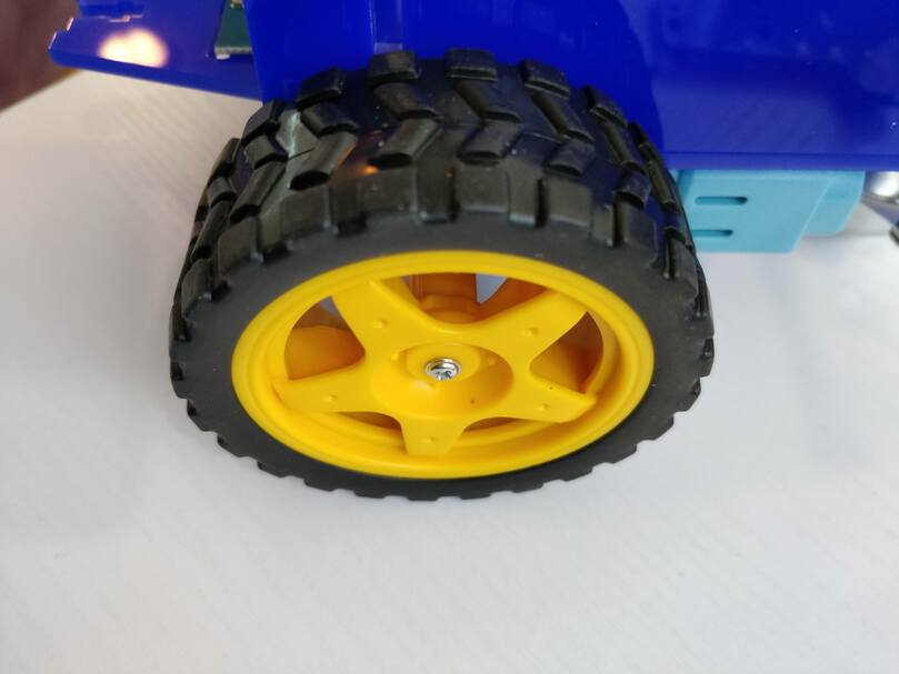
Fig. 36 Screws will keep the wheels in place. Do not tighten too hard!#
Troubleshooting
SYMPTOM
My Duckiebot is driving backwards when pressing the key for straight forward.
RESOLUTION
Try swapping the motor cables on the HUT connectors. Double-check the motor cables are connected to their respective ports as indicated above.
Troubleshooting
SYMPTOM
I don’t understand what’s going on with the connections!
RESOLUTION
This simplified block diagram of data and electrical connections of the DB21M might help:
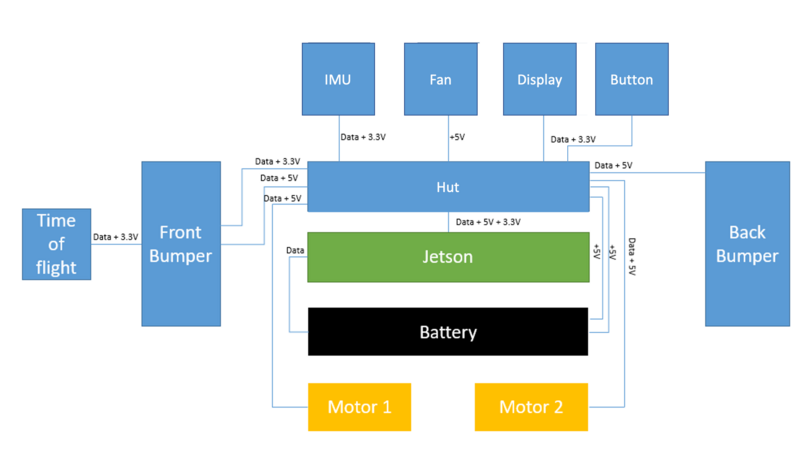
Fig. 37 Block diagram of electrical and data connections for the DB21J and DB21M.#
Troubleshooting
SYMPTOM
ToF sensor not detected
RESOLUTION
If you have Jetson Nano with 2 camera ports, try to plug ToF into CH4 instead of CH6 on the front LED bumper board.
Troubleshooting
SYMPTOM
“Bad Gateway” error on the Dashboard
RESOLUTION
Double check all i2c cable connections: (a) front bumper, (b) time-of-flight sensor, (c) IMU, (d) back bumper, (e) screen.
Troubleshooting
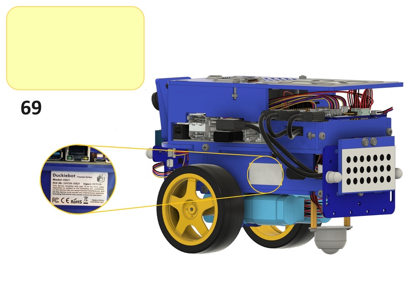
SYMPTOM
I have a non-functional sticker with weird symbols left over. What to do with it?
RESOLUTION
Duckiebots are FCC and CE certified, which means they comply with (and surpass) material quality (e.g., RoHS 2.0) and electrical interference standards (FCC, CE). You should place the sticker somewhere on the Duckiebot. We suggest a position out of sight (of other Duckiebots) to prevent detection issues in more advanced applications. For example, under the wheels:
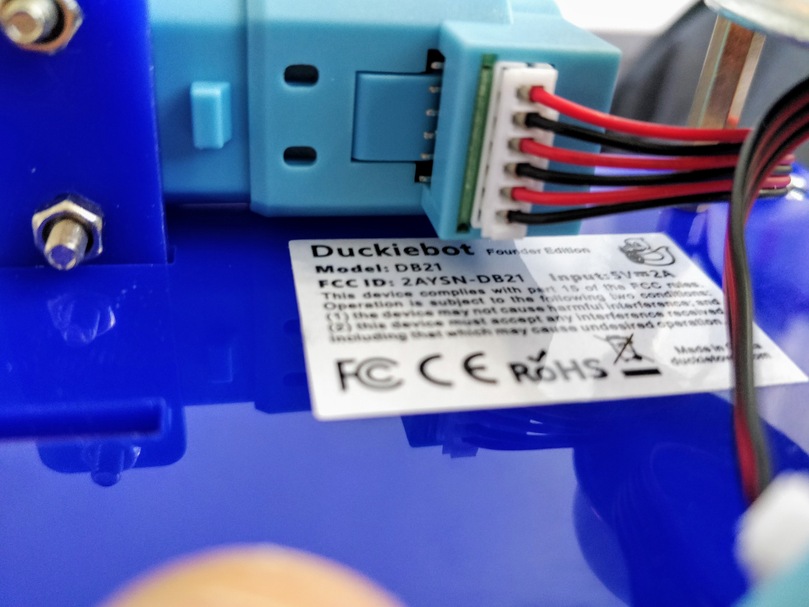
Fig. 38 Place the sticker somewhere a human can read it, but another Duckiebot cannot.#
Troubleshooting
SYMPTOM
I followed the instruction to the letter, but there is something off I can’t quite put my finger on.
RESOLUTION
You forgot to put a duckie on top of your Duckiebot!