Assembly - Duckiebot DB21M
Contents
Assembly - Duckiebot DB21M#
Attention
These instructions are not of the latest Duckiebot model. Unless you are handling a legacy Duckiebot (version DB21M), you should follow these instructions instead: DB21J assembly instruction.
See also
Not sure what is your Duckiebot? Read more about Duckiebot configurations.
What you will need
Duckiebot
DB21Mparts (get aDB21M). If you are unsure what version of Duckiebot you have, check this overview of all existing Duckiebot configurations.A micro SD card with the Duckiebot image on it. The procedure to flash the SD card is explained here.
3 hours of assembly time.
What you will get
An assembled Duckiebot in configuration
DB21M.
Foreword#
These instructions are your friend. Follow them carefully, especially if it’s the first time you assemble a DB21M. Small variations might cause big effects (e.g., don’t flip your cables!).
Video tutorial#
What’s in the box and assembly video
Duckiebot DB21M unpacking and assembly from Duckietown on Vimeo.
Overview#
A Duckiebox contains the following components:
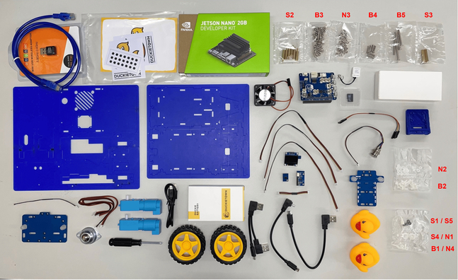
Fig. 39 Overview of all parts in your Duckiebox#
The assembly process is divided in 9 parts. They must be completed in the following order:
The Troubleshooting section at the bottom of this page provides resolutions to common symptoms.
Preliminary Steps#
Unboxing#
Unbox all of your components and lay them out on a flat surface. Ensure that you have well lit, uncluttered space to work on.
Tip
“The Duckiebox hides but does not steal”. Your Duckiebot chassis is under the white protection foam. To get to the chassis, pull out the white foam from the box after removing everything. Mind that the upper part of the inside foam has several side pockets in addition to a main compartment where components are located.
Although not necessary, a small (M2.5) wrench might ease some of the next passages.
Plastic cover#
Peel the plastic cover from all the chassis parts on both sides.
Screws, Nuts and Stand-offs#
Each type of screw, nut and stand-off is labeled with an index. You will find corresponding labels on the pictures at each step. Using the right parts at each step will prevent undesirable effects (e.g., nylon screws prevent electrical shorts).
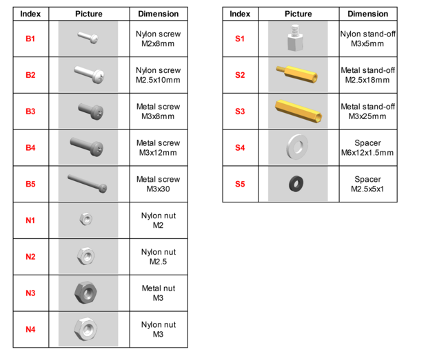
Fig. 40 Overview of interlocking parts#
Drive Train#
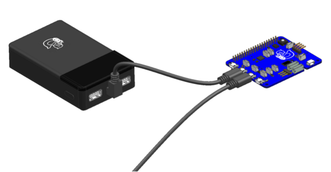
Step 0 - Charge battery via HUT#
Connect the battery and the HUT board as shown and make sure a green LED on the HUT is lit.
Wait 30 minutes and then push the button on the battery.
Check that the state of charge LEDs on the battery start blinking.
Leave this setup until the battery is fully charged. This may take up to 5 hours.
In the following steps (1 to 12) you will build the base plate assembly.
Step 1#
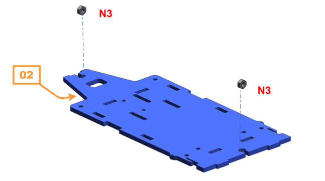
Take the baseplate (number 02 on the bottom side) and insert two metal M3 nuts (N3) as shown.
It might appear tricky at first to make the nuts fit. Once on the inset, gently rotate each nut until it falls in place (note the final orientation of the screw in the picture).
Note
Occasionally manufacturing tolerances (on the nut and the laser cut chassis) might prevent a flush fit. Trying a different nut or changing the insert direction might solve the problem.
Step 2#
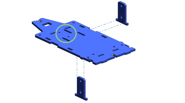
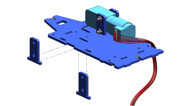
Check the hole pattern in the middle of the plate to make sure you are holding it the right orientation, then insert two of the motor plates in the base plate.
Step 3#
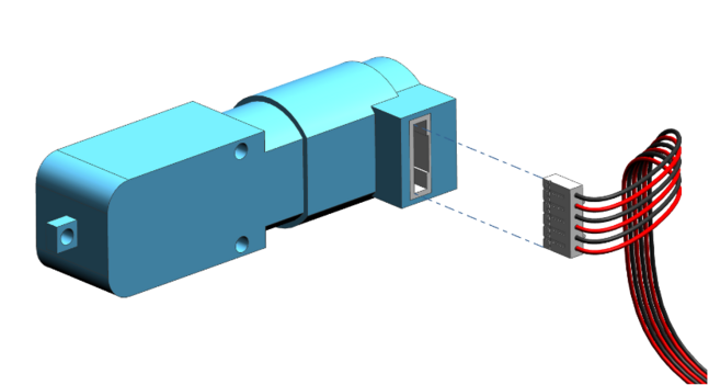
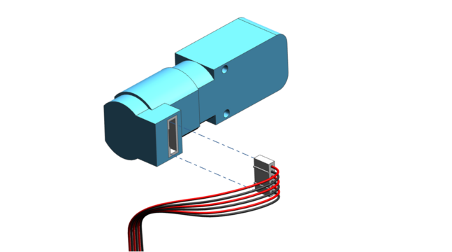
Connect one of the 6-pin motor cable to the blue motor.
Tip
It might be easier if you place the base plate on a flat surface so hold the motor plates. Use one hand to hold the nut, and the other to drive the screwdriver.
Step 4#
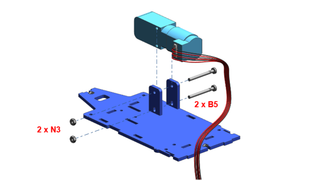
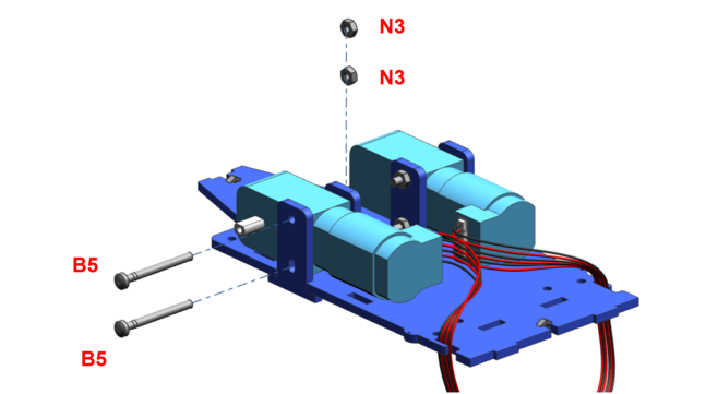
Place the motor between the two plates and tighten it with two M3x30 screws (B5) and two metal M3 nuts (N3). Tighten the screws enough so that the final assembly does not wobble. Don’t use excessive force to avoid getting hurt (or braking something).
Warning
Pre-bend the cable before carefully passing it through the cable management inset on the chassis. Don’t use force to avoid braking the inset.
Step 7#
Tighten the second motor with two M3x30 metal screws (B5) and two metal M3 nuts (N3) and place the cable, similarly to steps 3 and 4.
Step 8#
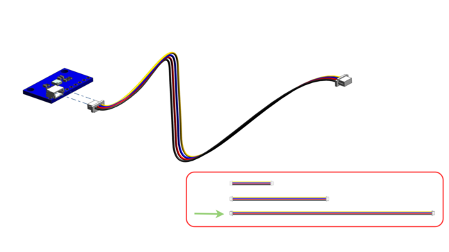
Connect one of the longest 4-pin cables to the white connector of the IMU (Inertial Measurement Unit) board.
Step 9#
Attach the IMU board to the base plate using two nylon M2.5x10 screws (B2) and two nylon M2.5 nuts (N2).
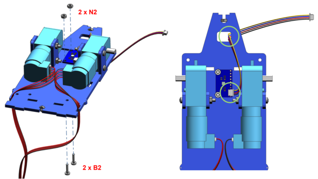
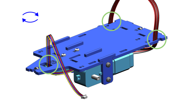
Step 10#
Flip the assembly and verify that the three cables are routed through their corresponding holes or slits (cable of the left motor through the left slit, cable of the right motor through the right slit).
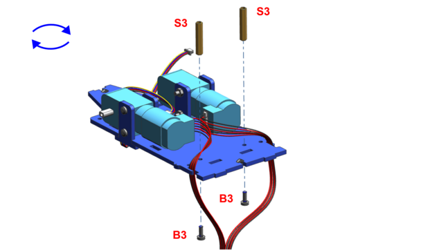
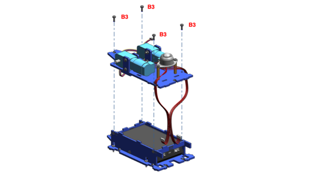
Step 11#
Flip the assembly again and mount the two M3x25 stand-offs (S3) to the bottom plate. Use two metal M3x8 screws (B3).
Step 12#
Mount the omni-wheel to the stand-offs using two of the metal M3x8 screws (B3).
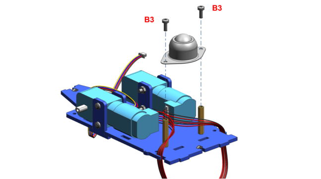
Tip
If you note the screws don’t go all the way, try flipping the stand-off.
Verify the assembly#
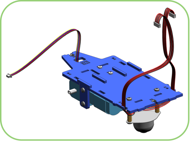
Before proceeding, verify that no component is wiggling. The only things moving should be the cables and the sphere in the omni-wheel (and, yes, the motor axles). Proceed to gently tightening the screws of the offending parts, if necessary.
Congratulations, you just built the base plate Duckiebot assembly!
Battery Pack Installation#
The following steps (13 to 18) guide through the Duckiebattery assembly:
Step 13#
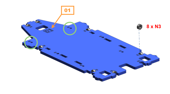
Take the upper plate (01) and 8 metal M3 nuts (N3). Compare the hole in the green circles with the hole position on your plate and make sure they agree (if the number 01 is visible on top, you are good to go).
Step 14#
Insert 4 nylon M2.5x10 screws (B2) from the top and tighten them with 4 nylon M2.5 nuts (N2).

Step 15#
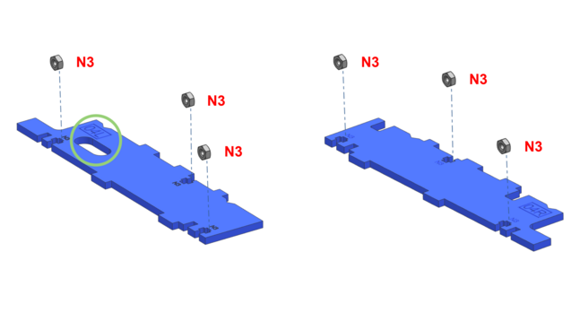
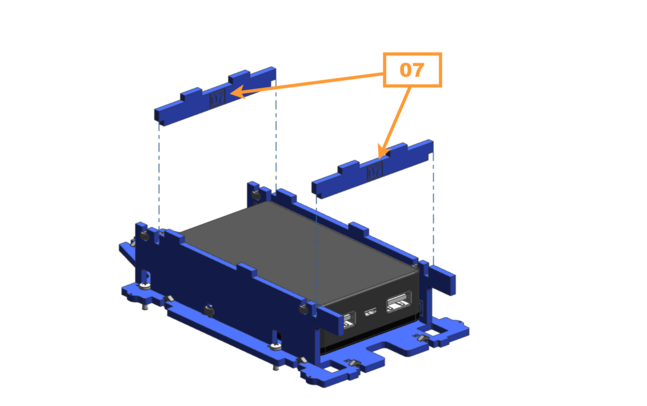
Take the two plates with numbers 04L and 04R and insert three metal M3 nuts (N3) into each of them.
Step 16#
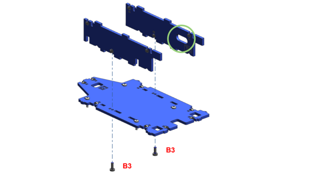
Connect these two plates to the upper plate with a metal M3x8 screw (B3) each. Note the slightly different holes in the side plates to mount them in the right way!
Step 17#
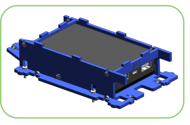
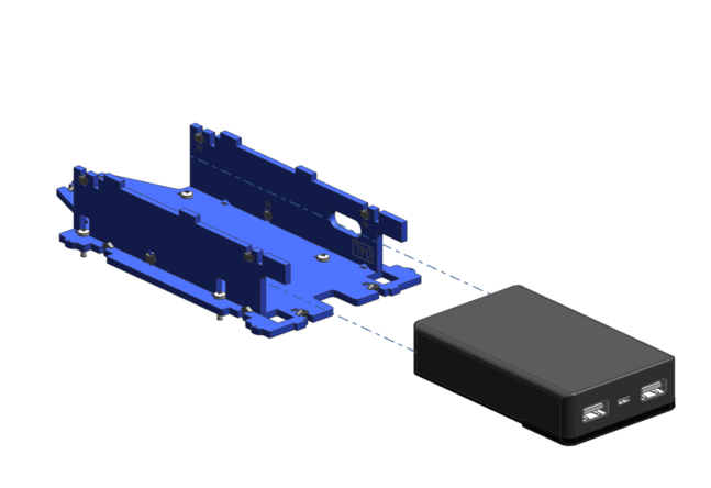
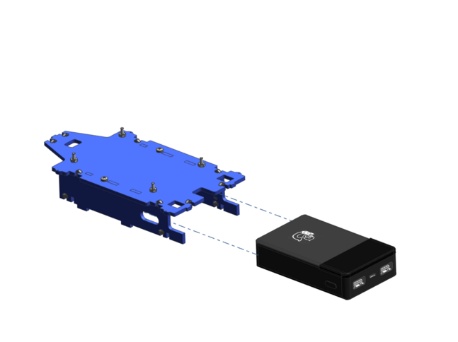
Insert the battery between the two side plates. Make sure the Mack the duck is on the bottom. The USB ports of the battery are not the same. Flipping the battery at this stage will cause the Duckiebot not to power on.
Computation Unit and Rear Assembly#
At this point, we are starting to see the final shape of the Duckiebot! The following steps (19 to 27) will help assemble the lower frame and mount the NVIDIA Jetson Nano board:
Step 19#
Take the lower half of the Duckiebot from steps 1 to 12 again and mount it directly to the assembly you have just created using 4 metal M3x8 (B3) screws. Make sure all the plates are locked in place correctly.
Attention
This is a tricky step and might require a few tries to get it right. Remember that the Roboticist is patient and welcomes challenges with joy and determination!
Step 20#
Check the routing path of the two motor cables again from step 10 and wire them through the holes in the upper plate.
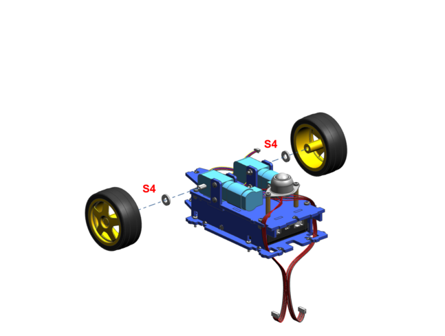
Step 22#
Take the two yellow driving wheels and push them to the motors using one distance disk (S4) between each of them.
Step 23#
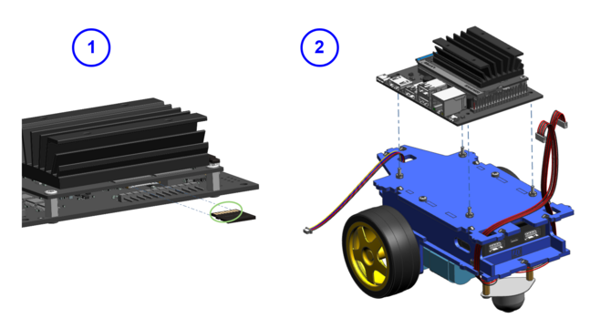
Insert the SD card to the slot on the NVIDIA Jetson Nano board. Make sure the metal pins of the SD card are facing the heat sink.
Place the Jetson Nano on the 4 screws from step 14 but DO NOT tighten the Jetson with any nuts or stand-offs yet!
Step 24#
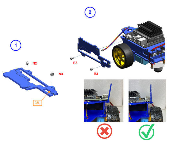
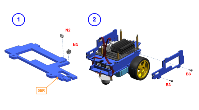
Take the side cover carrying the number 05L. Insert a nylon M2.5 nut (N2) and a metal M3 nut (N3) into the plate (note the engravings: N2 and N3 on the plate itself).
Then secure the plate to the frame using two metal M3x8 screws (B3).
You may need to lift the Jetson Nano a little to fit the side cover plate under the NVIDIA Jetson Nano board.
Step 26#
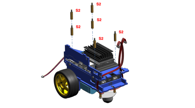
Tighten the NVIDIA Jetson Nano board with the 6 brass stand-offs (S2). Put two stand-offs on each of the front screws but only one each on the back.
Step 27#
Take the side cover carrying the number 05R. Insert a nylon M2.5 nut (N2) and a metal M3 nut (N3) into the plate, similarly to step 24 (note the engraving: N2 and N3 on the plate itself). Then screw the plate to the frame using two metal M3x8 screws (B3).
Cable Management#
Step 28#
Take the USB cable that has three connectors. Connect the Duckiebattery and the NVIDIA Jetson Nano board with the USB-A ports as shown in the picture below.
Attention
The micro USB connector must not be connected at that stage!
Step 29#
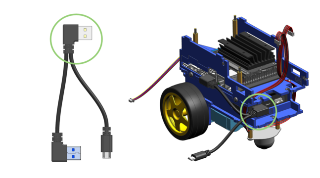
Take the angled micro USB to micro USB cable and plug the angled connector to the middle port on the Duckiebattery. Wire the cable through the chassis as shown in the picture below. The micro USB end must be unplugged at that stage!
Tip
An experienced Roboticist at this point would mark the free end of this cable (e.g., with a sticker or some tape), to make it distinguishable from the other free roaming cable with a micro USB connector, so to make it very improbable to mix the two up and prevent future headaches!
Step 30#
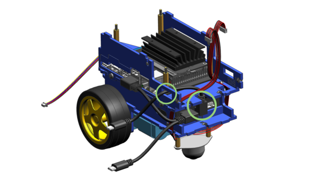
Now take the last USB cable, with a micro USB plug on one side and an angled USB-A plug on the other side. Connect the USB-A end to the last (right) port on the Duckiebattery. Again, wire the cable through the chassis as shown and leave the micro USB connector free on the other side.
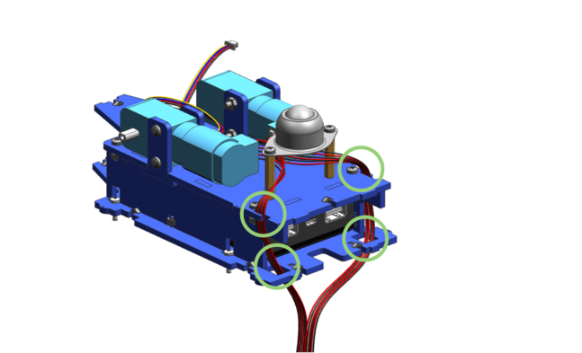
Step 32#
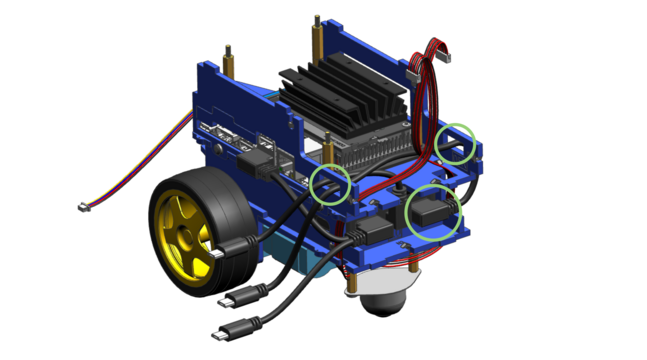
Take the back bumper board and connect the 4-pin cable of medium length to the white plug on the board.
Step 33#
Wire the cable attached to the back bumper through the same hole in the upper plate as the motor cable of the left driving motor.
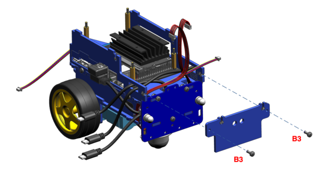
Step 34#
When attaching the back bumper board to the chassis, make sure the pins of the lower and upper plate all fit well. Tighten the board with three metal screws (B3).
Step 35#
Take the plate carrying the number 06 and press two nylon M2.5 nuts (N2) into the corresponding slits.
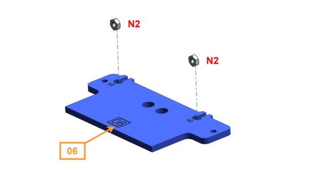
Step 36#
Mount the plate number 06 to the back of the chassis using two metal M3x8 screws (B3).
Attention
The 06 is not symmetric and the orientation matters. If the number 06 is pointing towards the Duckiebot, we are good to go!
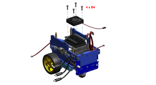
Step 37#
Take the fan and mount it on top of the heat sink of the NVIDIA Jetson Nano board using 4 metal M3x12 screws (B4). Make sure the cable of the fan is pointing to the back right side (it might be necessary to use a little force on these screws, as the thread has to cut it’s way through the heat sink the first time).
Note
You don’t need to tighten the screws completely but the fan must sit tight.
Step 38#
Take the PCB with the Duckietown logo on it (we’ll call it the HUT from now on. A DB21M is equipped with a HUT v3.1).
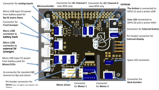
Plug in the fan cable to the two pins as shown (note the orientation of the black and red cables!).

Step 39#
Gently press the pin connector of the HUT on the pins on the NVIDIA Jetson Nano board. Make sure both motor cables are routed through the slit in the HUT board.
Step 40#
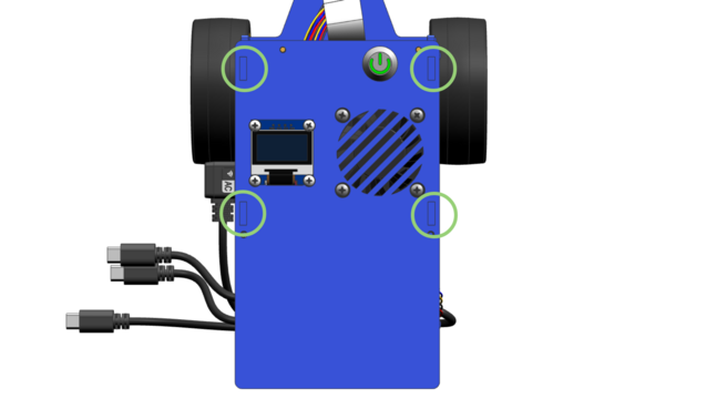
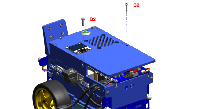
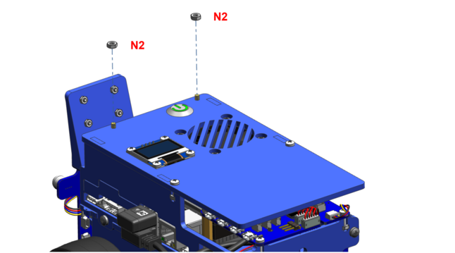
Connect the HUT to the plate in the back using two nylon M2.5x10 screws (B2). Make sure the end of the 4-pin cable connected to the back bumper board is pointing to the right hand side.

Step 41#
Connect the 4-pin cable of the back bumper board to the white connector in the back right corner of the HUT.
Step 42#
Connect the first 6-pin motor cable of the left motor to the connector placed on the edge of the HUT.
Step 43#
Connect the second 6-pin motor cable of the right motor to the other connector.
Note
If you swap the motor cables, you Duckiebot will probably drive backwards when it is supposed to drive forwards :)

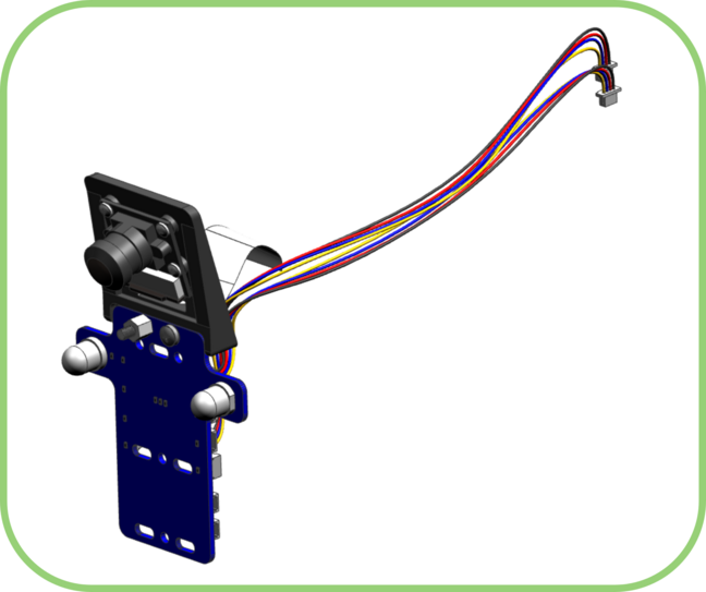
Front Assembly#
The following steps 45 to 52 will guide you through the assembly of the camera unit as well as some more electronics and cables.
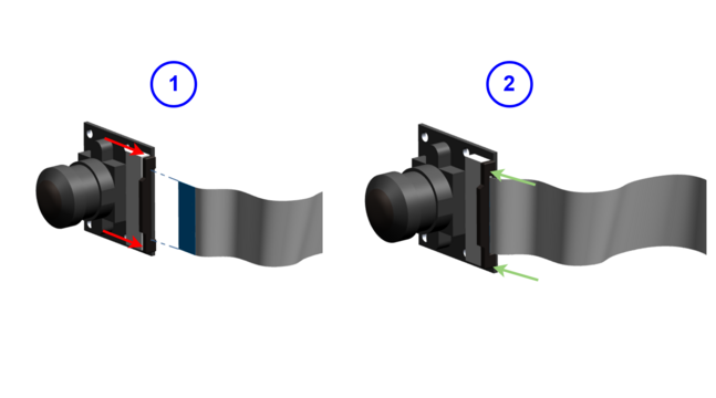
Step 45#
If not already done, open the plug of the camera and push one side of the camera cable in. The orientation of the cable should be such that the copper pins on the camera cable face the camera plate. Then close the plug completely. Make sure to take off the plastic cap from the lens.
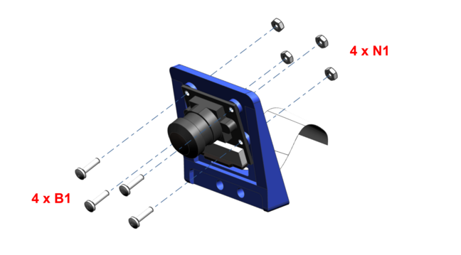
Step 46#
Wire the camera cable through the 3D printed camera mount starting from the front. Then use 4 nylon M2x8 screws (B1) and 4 nylon M2 nuts (N1) on the other side to tighten the camera to the mount.
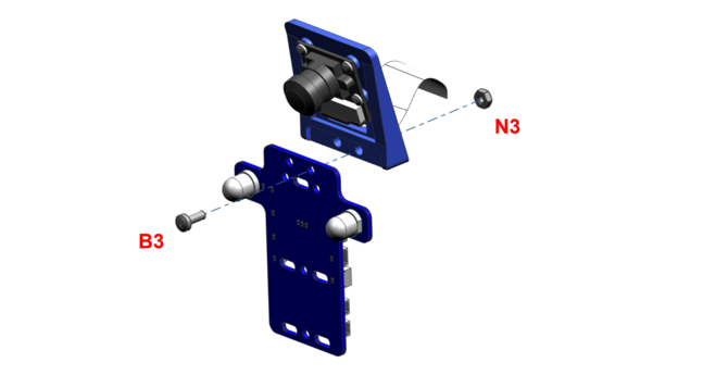
Step 47#
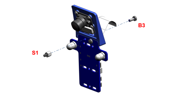
Mount the camera part to the front bumper board using only one metal M3x8 screw (B3) and one metal M3 nut (N3).
Step 48#
Mount the single nylon M3x5 stand-off (S1) with a metal M3x8 screw (B3) from the other side.
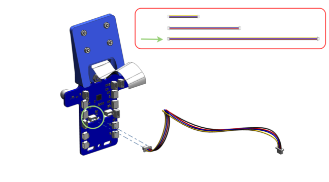
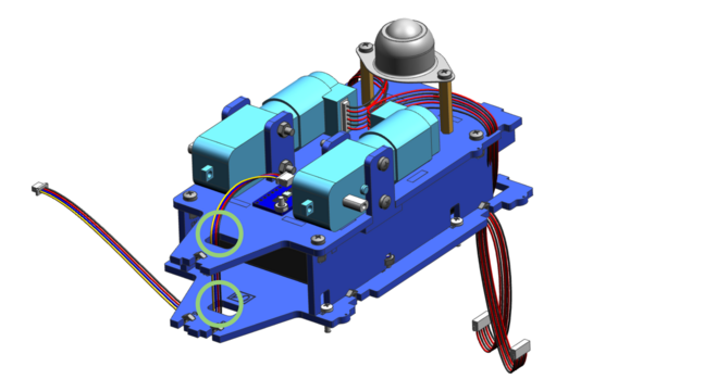
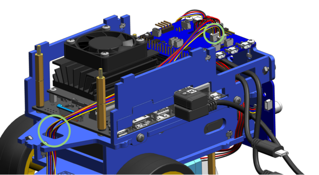
Step 50#
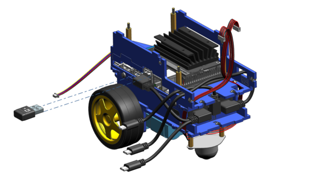
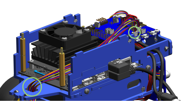
Wire the cable that you have just connected (step 49) through the upper plate and the connect it to the connector on the HUT, as shown below.
Step 51#
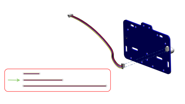
Take the last of the long 4-pin cables and connect it to the front bumper board, similarly to step 49.
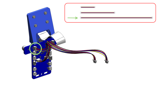
Step 52#
Again, wire this cable through the upper plate and connect it to the HUT, similarly to step 50.
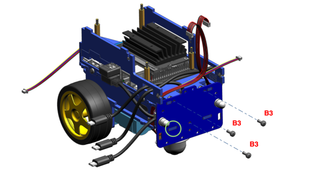
Step 53#
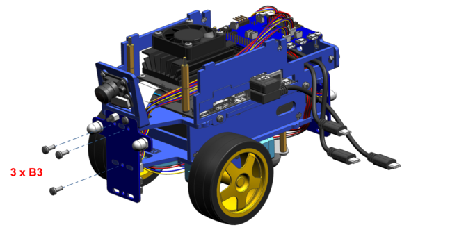
Mount the front bumper board to the upper and lower plate using three metal M3x8 screws (B3). Make sure they are locked in place correctly.
Step 54#
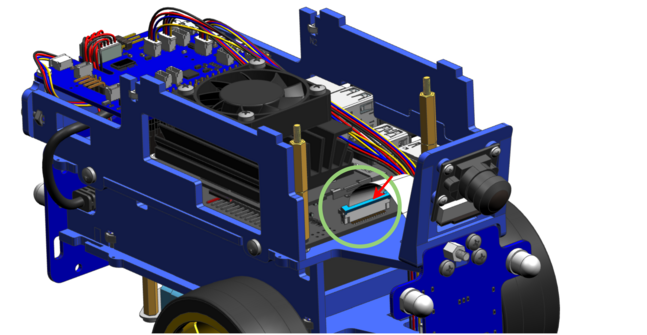
Open the camera slit on the NVIDIA Jetson Nano board by raising it on the sides (with care), and put in the other end of the camera cable.
Attention
The orientation of the cable should be such that the blue part of the cable faces the camera (i.e., facing towards the front end of the Duckiebot).
Step 55#
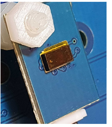
Attach the small blue distance sensor to the stand-off on the front bumper and tighten it with a nylon M3 nut (N4).
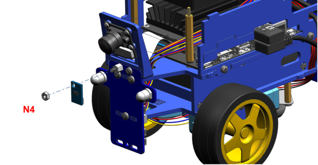
Make sure to take off the small transparent cover from the sensor.
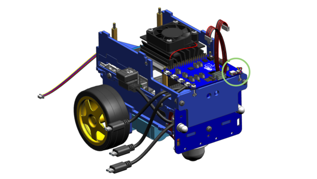
Attention (04/2023)
Do not proceed to Step 56.
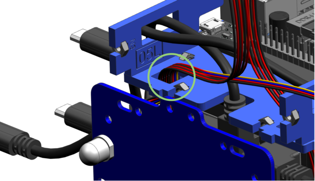
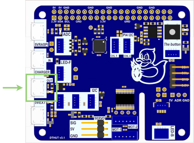
It is now recommended that you connect your ToF Sensor directly to the Duckiebot HUT. To do this:
Locate the 260mm cable that you connected to the I2C port on the front bumper in Step 49.
Disconnect the cable from the front bumper I2C port. Do not disconnect the other end of the cable from the HUT.
Connect the now free end of the cable into the ToF sensor port shown in Step 56.
Disregard Step 56.
You can now continue on to the Top Plate Assembly
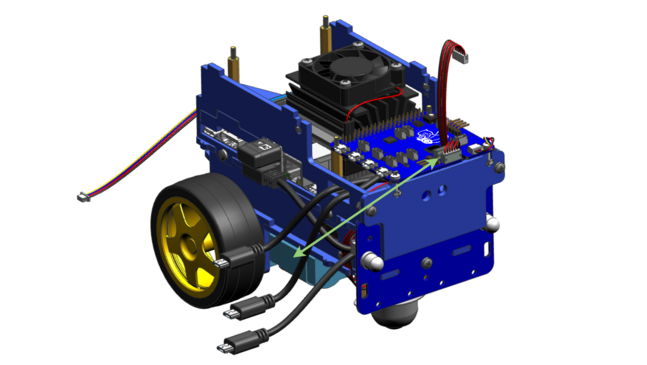
Step 56#
Take the shortest 4-pin cable and connect the bottom of the time of flight sensor to the front bumper, as shown below.
Top Plate Assembly#
The following steps 57 to 64 show the assembly of the top plate of the DB21M, containing a button and a screen.
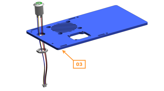
Step 57#
Remove the nut from the button, if necessary, and wire the button cables through the hole on the top plate (marked as 03).
Attention
Mind the orientation; if the number is pointing downwards, we are good to go!
Once the button is pushed in completely, tighten it again with the flat nut.
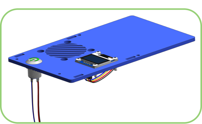
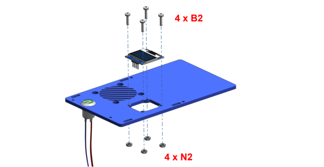
Step 58#
Mount the screen to the plate in a way the pins of the screen are pointing towards the button. Use 4 nylon M2.5 screws (B2) and 4 nylon M2.5 nuts (N2) for this.
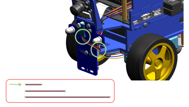
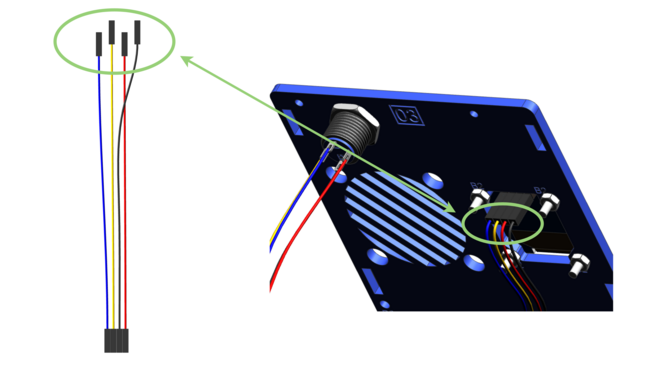
Step 59#
Have a look at the pin descriptions on the screen. Take the 4-pin cable with the long black connectors and connect the 4 loose ends to the screen.
Follow this pattern: GND-black, VCC-red, SCK-yellow, SDA-blue.
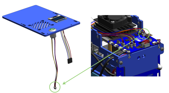
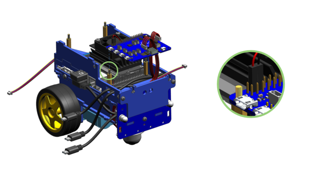
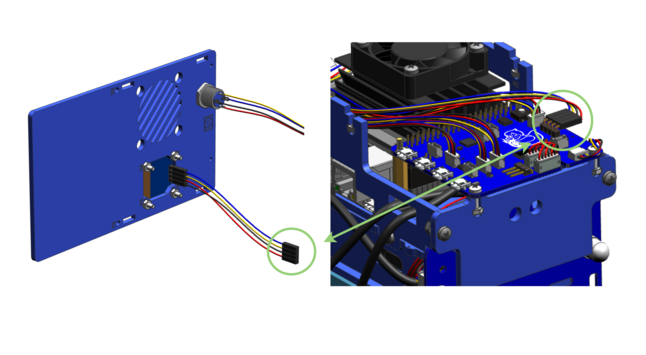
Step 61#
Connect the end of the cable from the screen to the 4 male pins on the HUT as shown. Check the colors of the cables so that the same goes to the same, i.e.: GND-black, 3.3V-red, SCL-yellow, SDA-blue.
Step 62#
Gently place the cover plate on the chassis. Make sure the screws of the fan and the pins of the side plates are locked in place properly.
Power your Duckiebot#
In this step we will plug the various power cables to the HUT. One port will remain free. You can use this port to charge the Duckiebot.
Warning
Always plug and unplug USB cables from the HUT with care!
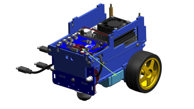
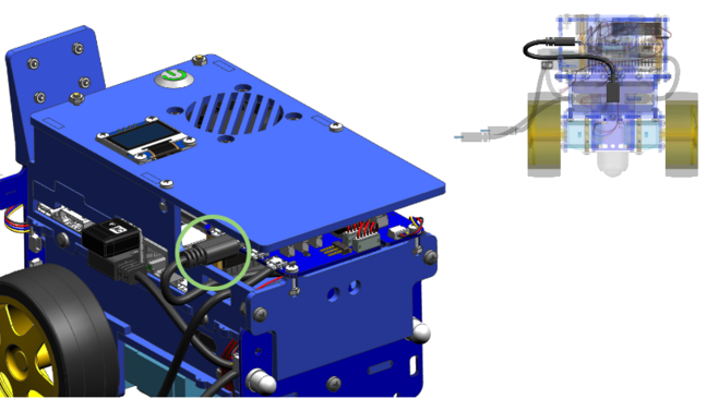
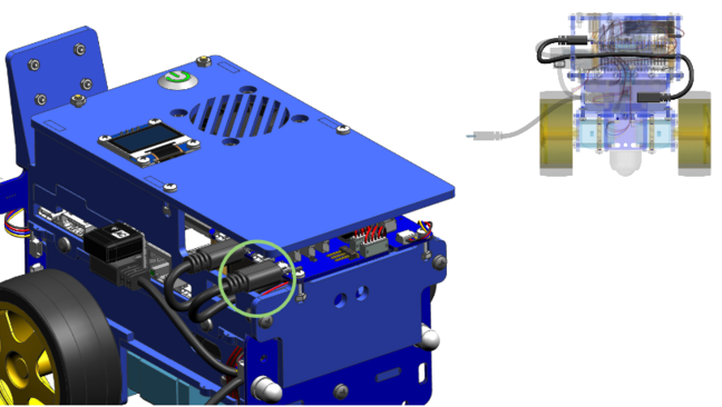
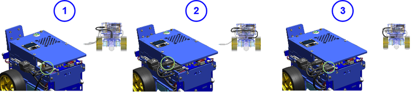
Step 65#
Take the black USB cable that you have connected in step 29 and connect it to the micro USB connector on the HUT as shown.
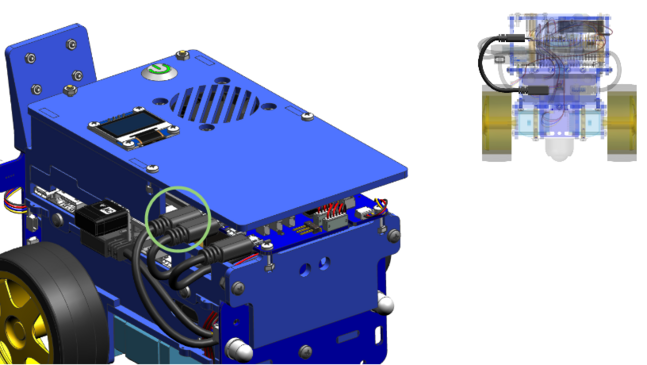
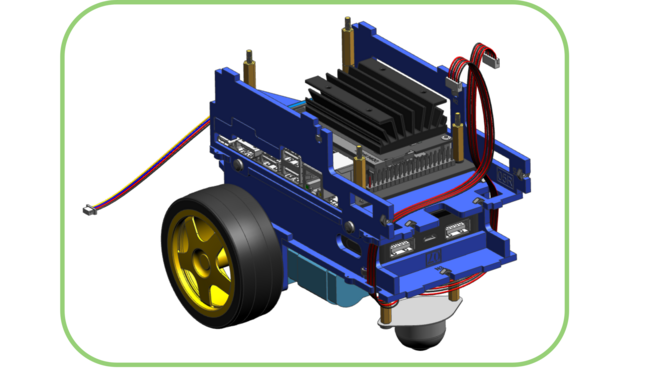
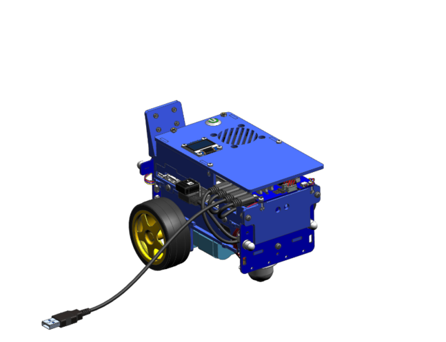
Step 68#
At that point, your Duckiebot is fully assembled!
For charging, connect the charging cable to the last free micro USB connector on the HUT. To avoid putting additional stress on the connector, you can leave this cable plugged in and store it somewhere under the blue top lid.
Once your Duckiebot is fully charged, you can press the button of the battery on the side to power it up (do this ONLY if a flashed SD card has been inserted).
Additional Parts#
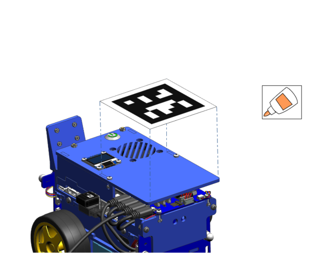
Step 69#
If you have an April tag take some glue and put it in between the two nylon screws on the top of you Duckiebot.
Check the outcome#
Look at the Overview of interlocking parts and make sure you have used each type at least once.
Check all cable connectors and make sure they are plugged in completely. Do not use force on the Duckiebot, it is (almost) never useful and it might lead to undesirable outcomes.
Make sure all USB cables to the Jetson Nano and the
HUTare plugged in completely, and in the correct order. Several configurations exist for which the Duckiebot will do something, but only one, described above, is the correct one.Make sure you have flashed your SD card with the latest version of the Duckiebot
DB21Mimage.Note
Version 1.2.2 is the minimum requirement for enabling battery code updates. Make sure you have at least this version (>22 March 2021).
Make sure the SD card is inserted in Jetson Nano in the dedicated SD card slot under the main board. Do not plug it in the adapter and in a USB port. If you have already inserted a flashed SD card, you are allowed to push the magic button on the battery.
Troubleshooting#
Troubleshooting
SYMPTOM
I can’t find the blue chassis.
RESOLUTION
It’s under the white foam in the Duckiebox. Remove the inner packaging to access it.
Troubleshooting
SYMPTOM
Camera cable needs to be twisted to make the pins on the cable matching those in the connector. Is this normal?
RESOLUTION
Yes this is normal. It might look a little nicer if you wire the camera cable around the metal stand-off next to the plug.
Troubleshooting
SYMPTOM
The Duckiebattery does not fit flush in the compartment.
RESOLUTION
Position it as it fits (at an angle). It will make the assembly a little trickier but everything will work out in the end.
Troubleshooting
SYMPTOM
I don’t have enough screws of a specific type.
RESOLUTION
Each package has enough screws of each type, plus spares of some. It might happen to inadvertently use one type instead of the correct one, which will result in shortages towards the final stages. Following the instructions carefully will prevent this from happening.
Troubleshooting
SYMPTOM
I can’t screw the omni-directional wheel right; the screws don’t fit all the way in the standoffs.
RESOLUTION
Sometimes manufacturing inefficiencies make the thread inside the standoff shorter than it should. This happens only occasionally and it is not the norm. The solution is to orient, in case of need, the shorter threaded stand-off side towards above, on the side of the chassis.
Troubleshooting
SYMPTOM
A piece broke while I was trying to assemble it!
RESOLUTION
Mistakes happen. Some damages will not influence the functionality of the robot, others will be fixable at home with some tools, others could be showstoppers. Please take a picture of the damage and send an email to hardware@duckietown.com.
Troubleshooting
SYMPTOM
The wheels tend to fall off the motors.
RESOLUTION
You may remove the distance disks you put in step 22. But make sure that the wheels are still not touching the screws of the motor mounts.
Troubleshooting
SYMPTOM
My Duckiebot is driving backwards when pressing the key for straight forward.
RESOLUTION
You have swapped the motor cables. Please check the steps 42 and 43 again and make sure you connected the cables the right way.
Troubleshooting
SYMPTOM
One of the black USB cables is too short to connect it to the HUT.
RESOLUTION
The customized cables may undergo some manufacturing tolerances. If it does not fit, there is a second way to connect the cables. However, some minor functionalities might differ in that configuration (e.g. the fan might continue working when shutting down the NVIDIA Jetson Nano).
Troubleshooting
SYMPTOM
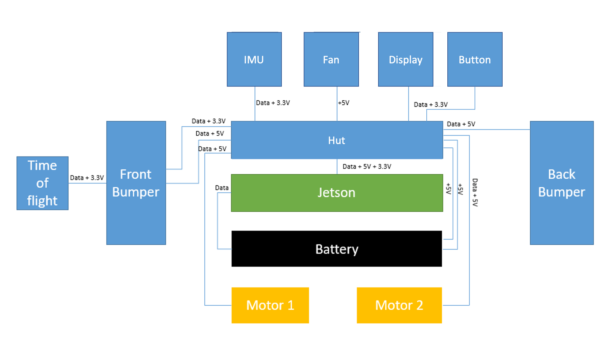
I don’t understand what’s going on with the connections
RESOLUTION
This simplified block diagram of data and electrical connections of the DB21M might help:
Troubleshooting
SYMPTOM
I followed the instruction to the letter, but there is something off I can’t quite put my finger on.
RESOLUTION
You forgot to put a duckie on top of your Duckiebot!