How to Use Multimeters
Contents
How to Use Multimeters#
During this step you will learn about how to use multimeters to do a continuity check and a voltage check.
A multimeter or a multitester, also known as a VOM (volt-ohm-milliammeter), is an electronic measuring instrument that combines several measurement functions in one unit. A typical multimeter can measure voltage, current, and resistance.
See also
This is a general tutorial for multimeters.
Attention
Please turn off the multimeter by setting the dial to OFF after you finish your check.
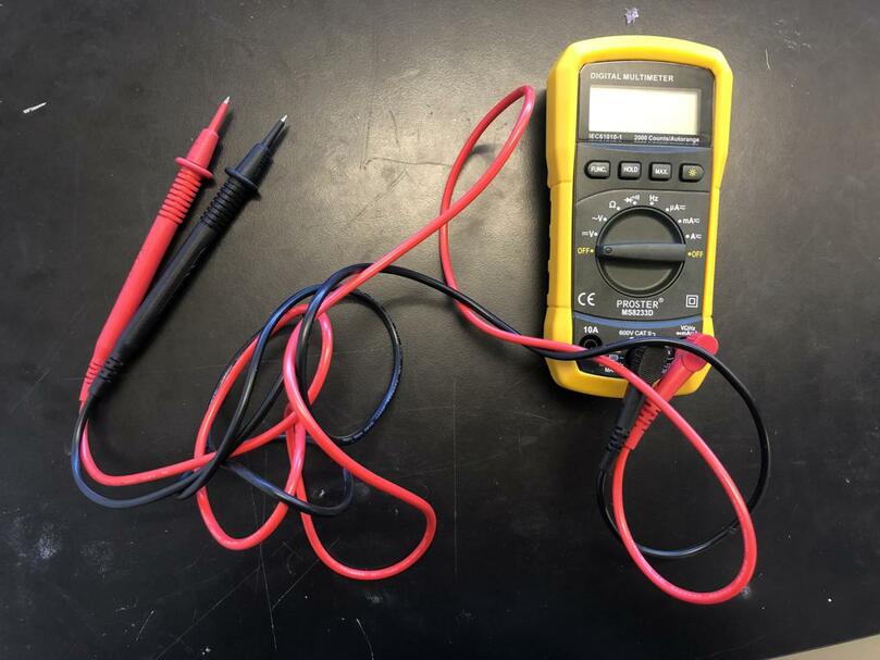
Fig. 2 Multimeter#
Continuity Check#
In electronics, a continuity check is a test of the resistance between any two points of a circuit (that it is in fact a complete circuit). If there is zero resistance between two points, then there is a short between the points. Shorts are potentially dangerous because they may cause far too much current to flow throughout the circuit - thus resulting in the circuit frying due to heat generated by Joule effect.
Note
There might be slight differences with your multimeter model, but the general instructions should be very similar.
Performing a continuity check is a safe way to debug if a circuit has an undesired short because the check does not require a power source to be connected to the circuit.
Select the Continuity Function
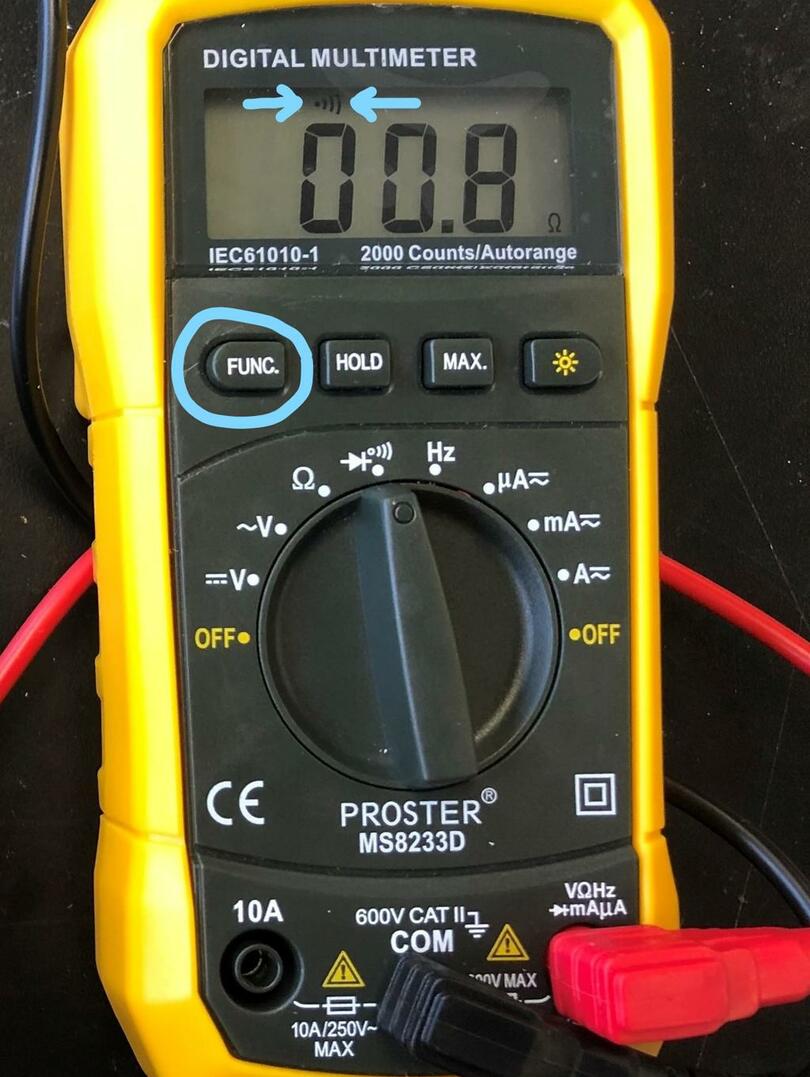
Turn the multimeter dial to the continuity test position. Then press the
"FUNC."button to switch to the continuity test mode (indicated by an icon that looks like a sound wave).Continuity test dial position
Continuity test mode
Test the continuity test mode by touching and holding the multimeter leads together. A continuous beep will be audible for as long as the leads are held together.
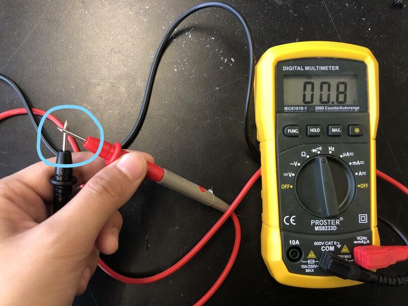
Fig. 3 Leads held together (a continuous beep is audible)#
Perform the Continuity Check
Place each lead at a point of the circuit or component you want to test.
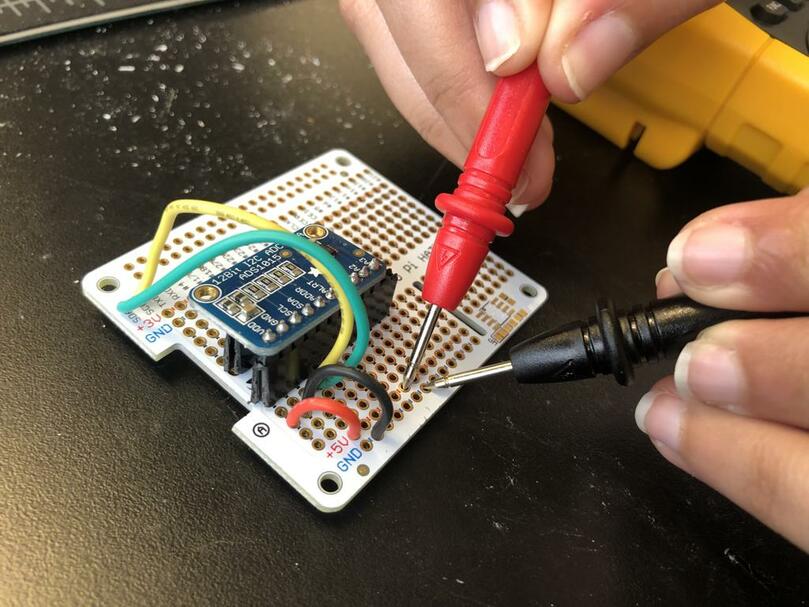
Fig. 4 Multimeter leads on breadboard#
If the path between the two points is continuous (i.e. is a short), then the screen will display a value of zero (or near zero) and the multimeter will emit a continuous beep for as long as the leads are held in place.
Note
If you hear a short beep followed by silence while the leads are held in place, then you can safely ignore the short beep.
General Continuity Check Strategy
Check every two positive (
+) terminals to make sure every pair of these terminals is continuous.Check every two negative (
-) terminals to make sure every pair of these terminals is continuous.Check every positive terminal (
+) to make sure it is not continuous with any negative terminal (‘-‘).
See also
DC Voltage Check#
Selecting the DC Voltage Mode
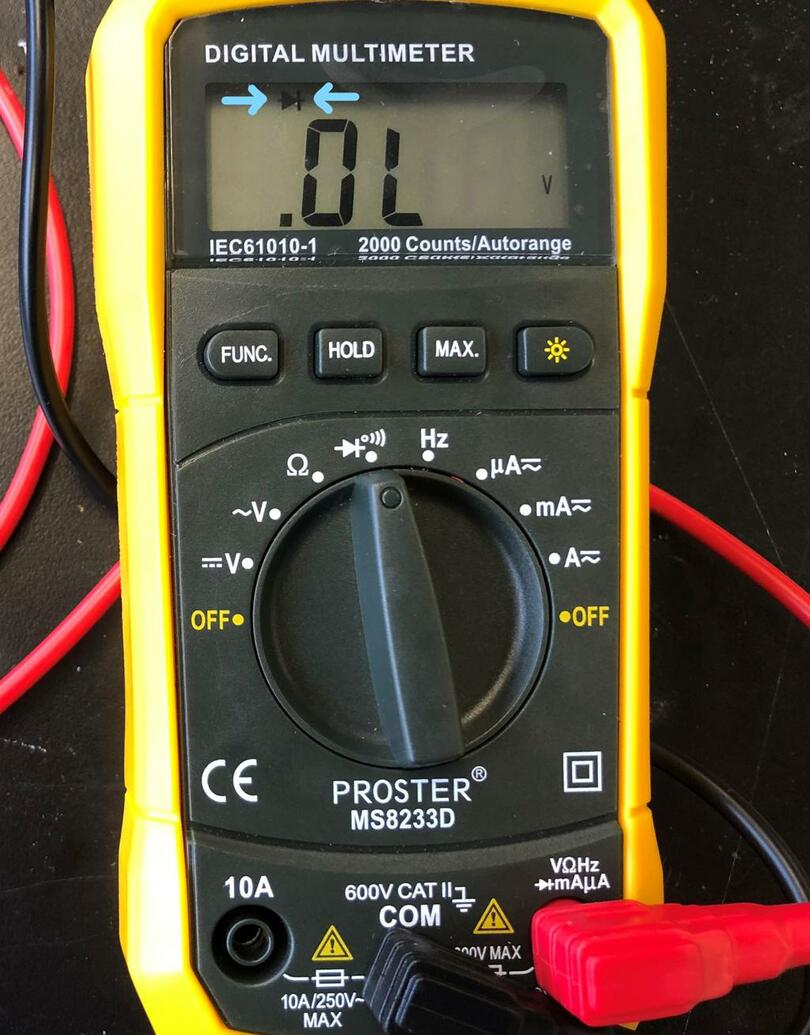
Switch on your multimeter, and set the dial to DC voltage mode (indicated by aVwith a straight line-V, or the symbol⎓).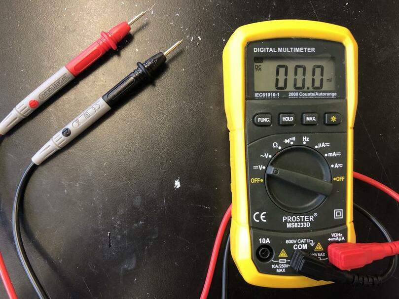
Fig. 5 Switch the Dial to the DC Voltage Test Function#
Performing the Voltage Check
Place the positive (i.e. red) lead on a positive (
+) terminal, and the negative (i.e. black) lead on the negative (-) terminal.See the screen for a voltage measurement.
Note
Reversing the leads (i.e. red on - and black on +) won’t do any harm; it will simply give a negative reading of the same magnitude.
See also
For an introduction or review of circuit basics and Ohm’s Law, \(V=IR\), check out this SparkFun article.