Overview
Contents
Overview#
Preface#
In this first part of the build, you will create a circuit to provide power to the Raspberry Pi from the battery. You will make the circuit connections using the soldering skills that you’ve gained from the Soldering Module.
First, we will introduce you to the components that you will be working with. Then, you will do some preliminary tasks that will run in the background. As those tasks are running, you will go through the first portion of the build.
Required Materials#
What you will need
Battery
Battery Charger
Battery Charging Adapter
Power Distribution Board (PDB)
Universal Battery Eliminator Circuit (UBEC)
Raspberry Pi Hat
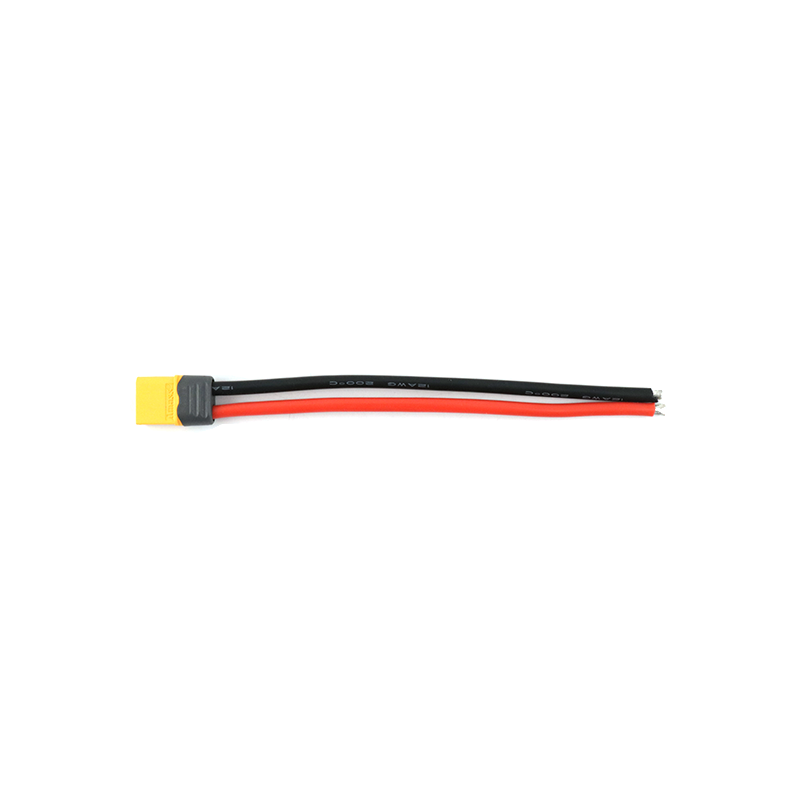
XT60 Connector
Soldering Tools
Raspberry Pi
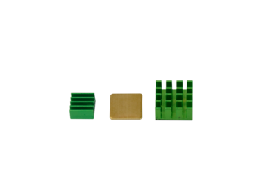
Heat Sinks
Micro SD Card
Base Station
What you will get
Assembled Raspberry Pi Hat and PDB
Detailed Hardware Descriptions#
Battery#
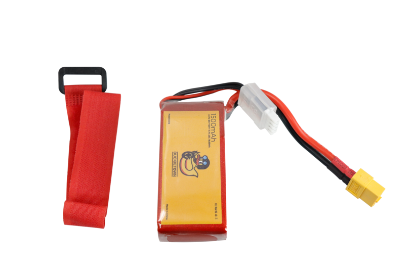
Fig. 26 LiPo Battery#
The Battery on your drone is a 1500mAh 3S 20C LiPo Battery. Let’s go over what all that means.
Capacity#
The unit milliampere-hour, or mAh, is a measure of how much charge a battery can hold. The higher this number is, the more charge the battery can hold; therefore, the battery will “last” longer and your drone will fly for a longer time without needing to be recharged.
Structure#
A Lithium-ion polymer (LiPo) battery is made up of one or more LiPo cells. Each cell has a voltage of 3.7 V when it is discharged, and 4.2 V when it is charged. The cells in your battery are connected in series, so that the voltages add together to get a total of 11.1 V when discharged, and 12.6 V when charged. There are three cells connected in series in your battery, so it is called a 3S battery.
Current Output#
The “C” rating of a LiPo Battery determines how much current the battery can deliver. The maximum current draw is equal to the battery’s C rating multiplied by the battery’s capacity. For the drone’s 1500mAh 20C batteries, the maximum current draw is 1500mAh x 20C = 30A.
Precautions#
Warning
Review the safety information on the battery.
Taking the proper precautions when using, storing, or charging is very important to keeping the battery safe.
Danger
Only store the battery at room temperature and out of direct sunlight.
Do not discharge a battery below 10.5 V.
Never leave the battery charging unattended.
Unplug the battery once it is fully charged.
Battery charger and charging adapter#
The battery charger and charging adapter allow you to draw power from an outlet to recharge the LiPo battery of your Duckiedrone. The blue charger has a display that cycles through showing the voltage on each cell and the overall voltage of the battery while it is charging.
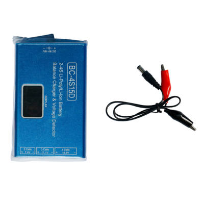
Fig. 27 Battery charger#
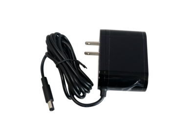
Fig. 28 Charging adapter#
Tip
During development/testing you might need to keep your drone on for more time than the battery allows.
A good solution for this scenario is to connect the Raspberry Pi to an external power supply, disconnecting the battery from the PDB.
In this way you can activate all the nodes (including Flight Controller) but the motors will not get power to spin.
Power Distribution Board (PDB)#
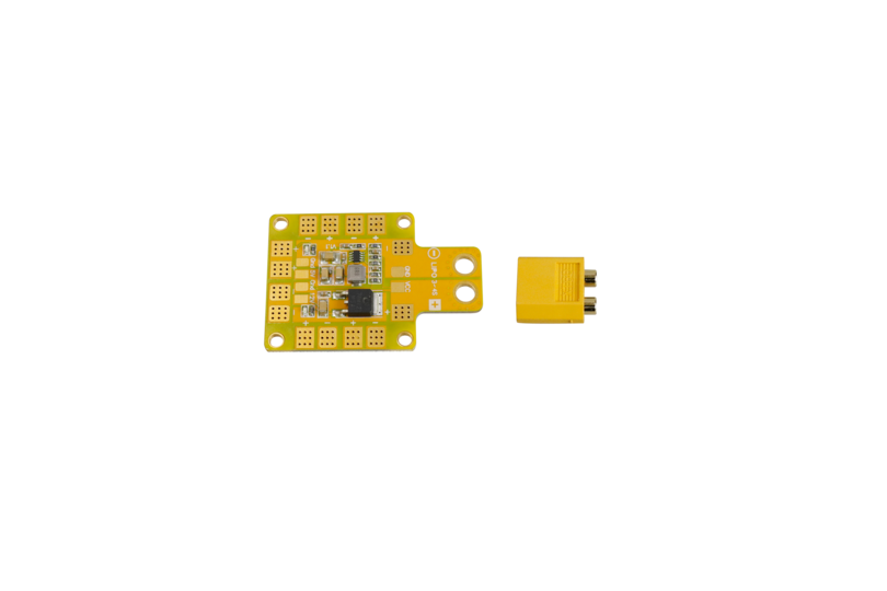
Fig. 29 Power Distribution Board (PDB)#
The Power Distribution Board is used to distribute power from the battery to electrical components of the drone. The PDB is an example of a Printed Circuit Board (PCB), which is a circuit board that has connections within its structure. For the PDB, the internal wiring connects all of the positive (+) pads together, and all of the negative (-) pads together; this allows for the battery to be connected to one set of positive and negative pads, and all of the other pads receive power.
UBEC (Universal Battery Eliminator Circuit)#
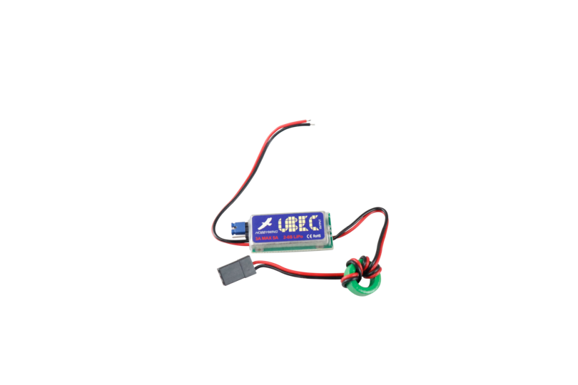
Fig. 30 UBEC#
The UBEC, solves the issue that arises from different electrical components requiring different supply voltages. In the case of the drone, the LiPo battery is used for outputs around 12V: this is the required voltage for the motors, but not for the Raspberry Pi, which requires 5V. The Universal Battery Eliminator Circuit eliminates the need to carry multiple batteries of different voltages by converting the 12V supply from the battery down to a 5V supply for the Raspberry Pi.
Raspberry Pi#
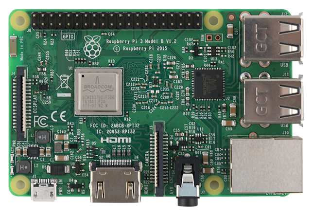
Fig. 31 Raspberry Pi 3 Model B#
The Raspberry Pi is a single-board computer. The Raspberry Pi is capable of running a full desktop operating system: you can use it as a computer similar to the one you’re using now. The Raspberry Pi is used on the drone as the main computer that reads and processes all the sensor data and user inputs, and then sends commands to the flight controller to control the drone motors. The drone would be able to fly without it if a person had a remote controller to manually steer the drone. However, for the Duckiedrone, the person with a remote controller is replaced by software and sensors on the Raspberry Pi. This, as well as the sensors you will connect later, makes autonomous flight possible.
Raspberry Pi Hat#
The Raspberry Pi Hat is a special type of breadboard. One useful property of a breadboard is that it has rails. A rail is a sequence of holes that share an electrical connection:
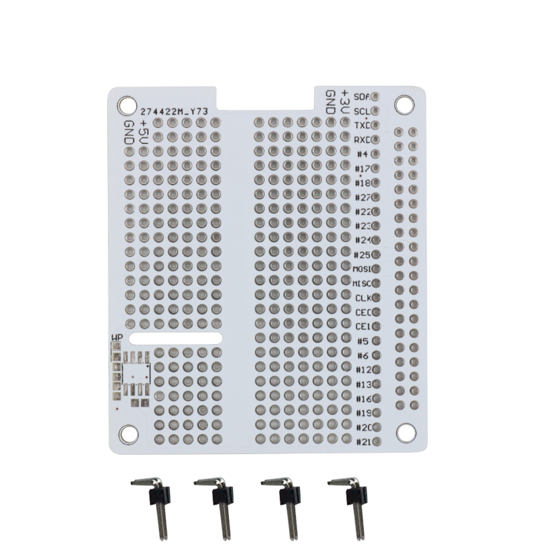
Fig. 32 Raspberry Pi Hat shield#
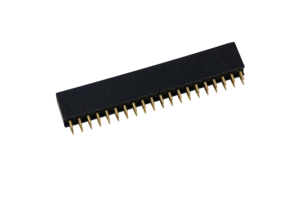
Fig. 33 Raspberry Pi Hat header#
The rails are useful because every wire put on a rail will be electrically connected; this means that it does not matter which hole along a rail a wire is inserted. This is useful for wire organization, and if a soldering mistake is made in one hole, an adjacent hole in the same rail can be used instead.
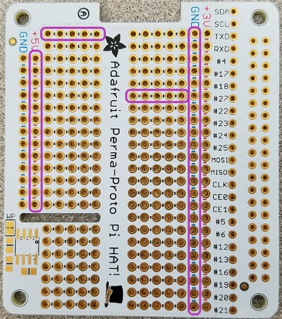
Fig. 34 PiHat with rails highlighted in purple#
Notice especially the long +5V and GND rails; we can use any of the holes in these rails to provide power to components. Also notice that there is a 3.3V rail, be sure not to mix this up with the 5V rail because electrical components will only work at the correct voltages.
Micro SD Card#
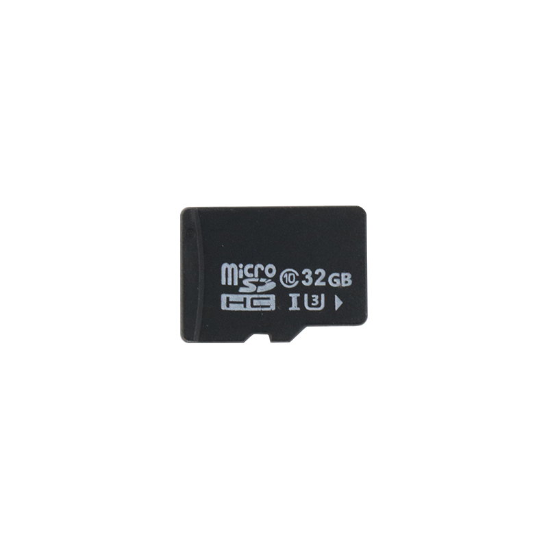
Fig. 35 microSD card#
The micro SD card stores the operating system on the Raspberry Pi, as well as all the software needed for autonomous flight.