Introduction
Contents
Introduction#
In this section, we will introduce you to the software of the drone, and how it interacts with the hardware you assembled. First, we will offer a brief explanation of the Robot Operating System (ROS), and the ways its tools are specifically implemented on the DuckieDrone to create the programs that allow the drone to fly autonomously. Next, we will look at a diagram which provides a visual overview of how all of the components needed to fly the drone fit together. Finally, we will describe each ROS node that is running while the drone flies to convert the data from the sensors into controls to the actuators (the four motors). In doing so, we will look closely at each component to understand its purpose, where it exists in the code, what ROS topics it interacts with, and what hardware it interfaces with.
The software architecture is designed to be modular and so that the code is extensible, or it is easy to replace each component when a better or different one when desired. The sensors are interfaced into ROS nodes which publish the data for the state estimator to combine into and estimate of the state of the drone. Based on this estimate, the controller (ours is a PID) is used to move the drone to a desired velocity or position based on the inputs from the web interface or a higher level behavioral engine. The mode controller ensures that the desired mode changes (such as ‘Armed’ to ‘Flying’) are legal, and will stop the flight if any safety checks failed (for example, the web interface heartbeat stops).
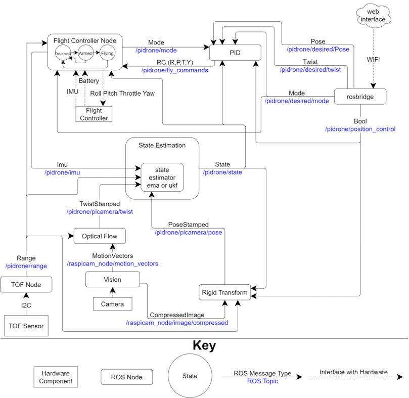
1.1. Diagram of the Software Architecture#
This is the general layout of the software architecture. Take a look at the key to better understand its meaning.