Instructions
Contents
Instructions#
Flight Controller soldering#
Here you will solder the Flight Controller.
Take the Flight Controller out of its plastic casing, exposing both sides of the PCB.
Soldering the ESCs pins#
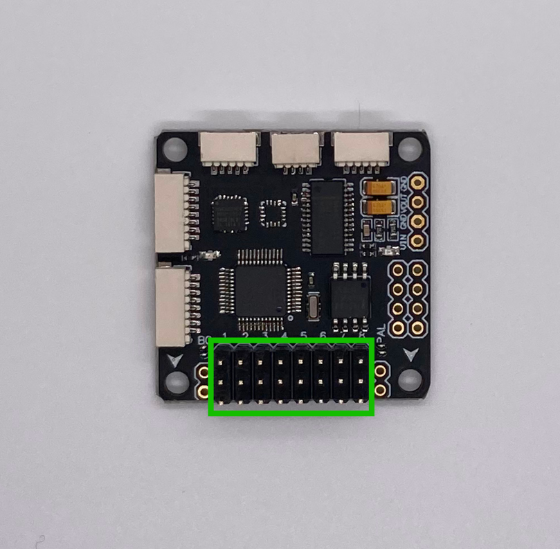
Here you will need to solder the pins to connect your ESCs to your Flight Controller.
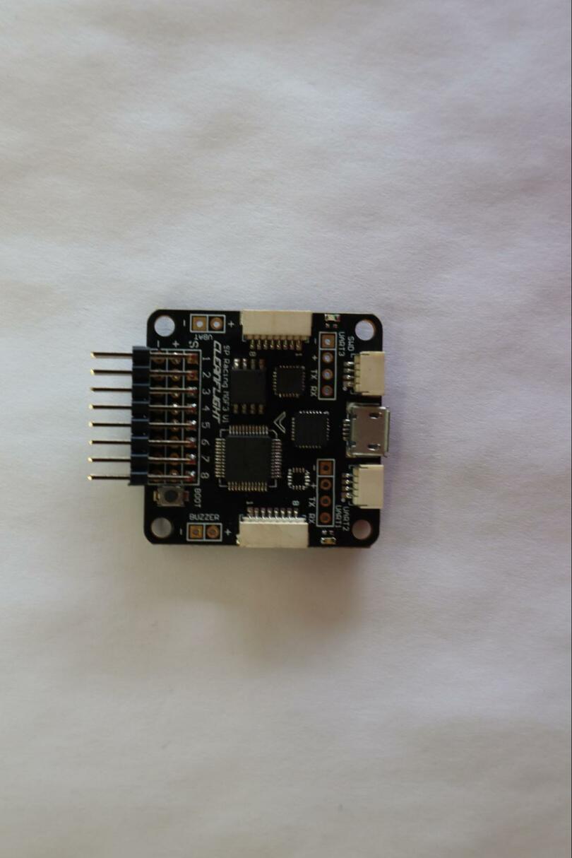
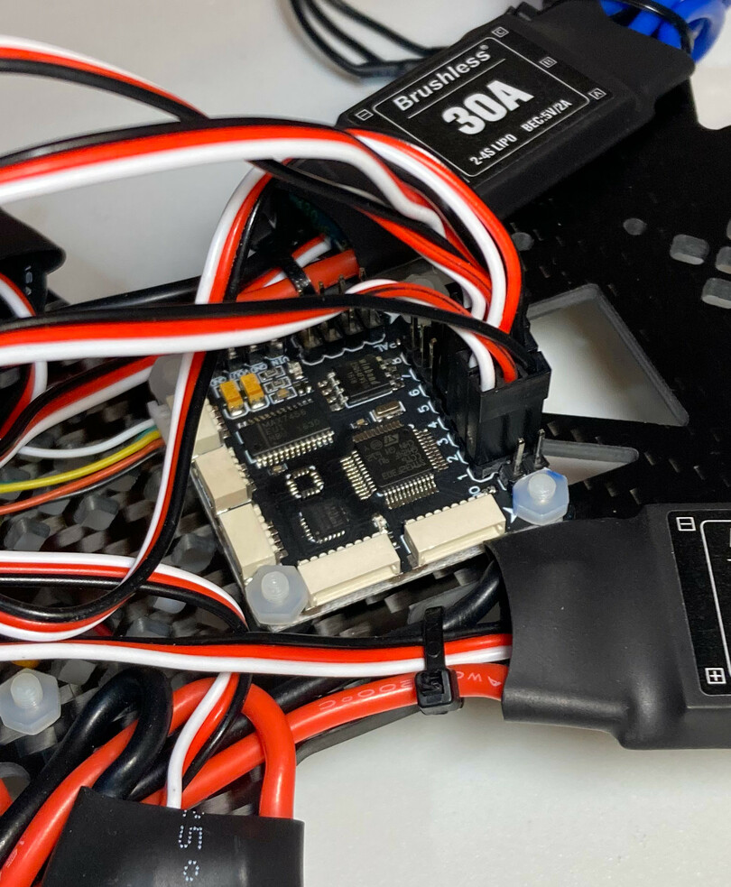
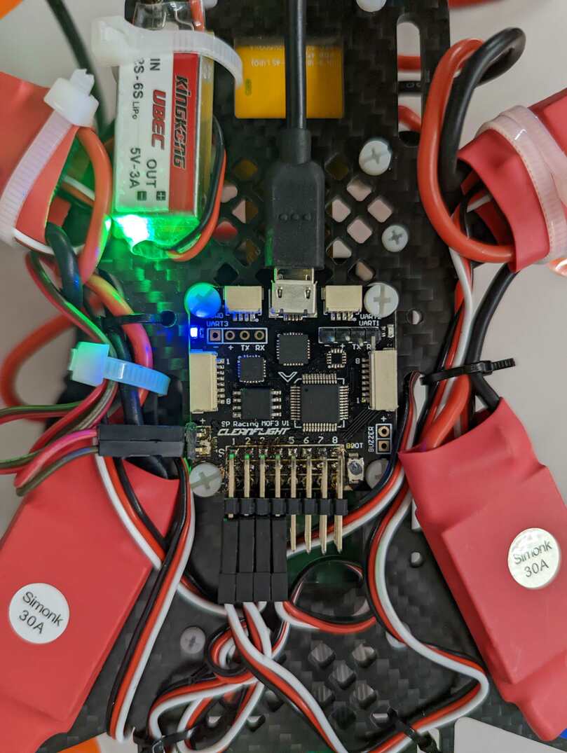
There are subtle variations between the two Flight Controller versions, choose in the tabs here your Flight Controller type.
Attention
Be sure that the direction you solder the pins into the board is exactly as shown in the images
Solder the battery monitor pins to the flight controller#
Pick the the 6 pins header that came in the Flight Controller wiring and use pliers to break off a 2 pins connect.
Solder the 2 pins connector to the flight controller, as shown in the image below (select your Flight Controller version in the tab).
Attention
The battery leads bins have to be soldered on the same side you soldered the ESCs pins on
The battery lead pins VBAT are in between the ESCs pins and the bottom-left mounting hole of the Flight controller.
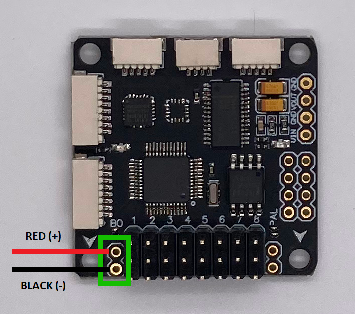
Fig. 82 Solder the battery leads pins to these two pads (they must stick out on the same side as the other pins)#
The battery lead pins VBAT are right above the bottom-left mounting hole of the Flight controller.
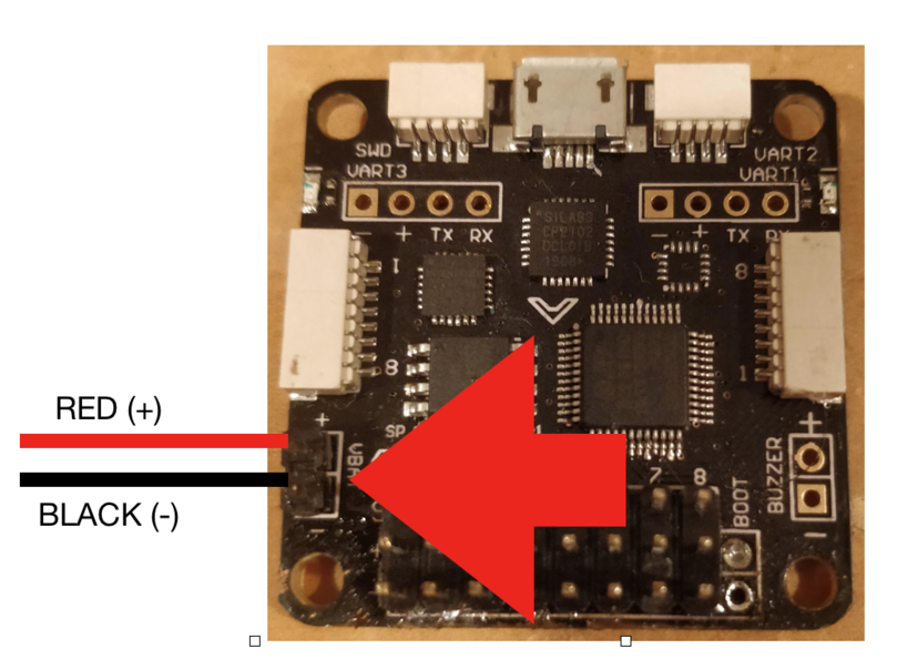
Fig. 83 Battery leads pins soldered#
Attaching the Flight Controller#
Now you will fix the Flight Controller to the Duckiedrone frame. The Flight Controller is located on the bottom side of the Duckiedrone, in the center (his “belly”).
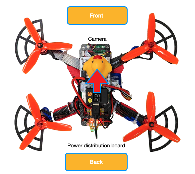
Fig. 84 Identify the front and back of your Duckiedrone#
The axes of the Flight Controller, according to the measurements of linear and angular accelerations provided by the IMU, are as follows:
uxis positive in the direction identified by the arrow serigraph on the PCB;uzis orthogonal to the plane identified by the Flight Controller’s PCB, and positive “coming out of the screen”;uyis such that (ux,uy,uz) is a right-handed reference system.
Attention
Make sure to orient the arrow on the Flight Controller towards the front side of the Duckiedrone.
Warning
This is a crucial setting. A mistake here will cause your drone to confuse left/right, up/down and most probably crash immediately.
To fix the flight controller to the frame use the 4 white M3 Nylon screws:
Insert the bolts from the front side of the frame.
Insert the rubber spacers on the bolt from the bottom side of the frame.
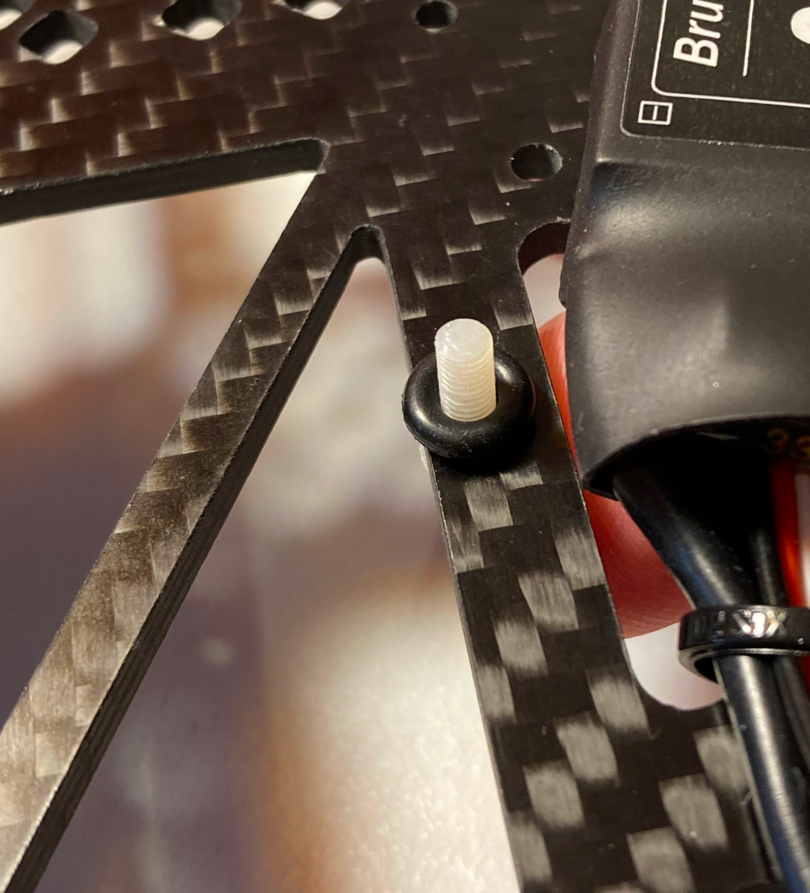
Screw the nuts on the bolts from the bottom side.
Attention
The OSD version of the Flight Controller has the soldered battery leads header pins partially occluding the space for the nut to be screwed.
The suggested solution is to simply file the nut about 1 mm to have enough clearance once screwed on the bolt.
In the end your Duckiedrone bottom should look like this:
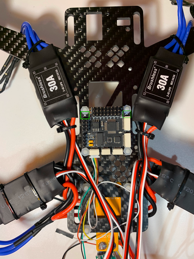
Fig. 85 Flight controller fixed to the bottom of the frame in the correct orientation#
(notice the arrows on the Flight Controller pointing towards the front)
Connecting the ESCs to the Flight Controller#
Now that the Flight Controller has been attached to the frame, it can be connected to the ESCs via the PWM wires (i.e. the thin white, red and black wires coming out of the ESCs).
Take a moment to find the numbers 1-8 next to the flight controller 3x8 header pins (the big row of pins that you soldered in).
We will be connecting the PWM wires to numbers 1-4 because we have 4 motors.
Attention
These numbers on the Flight Controller indicate which PWM wire coming out of the motor should be connected to which set of pins on the flight controller.
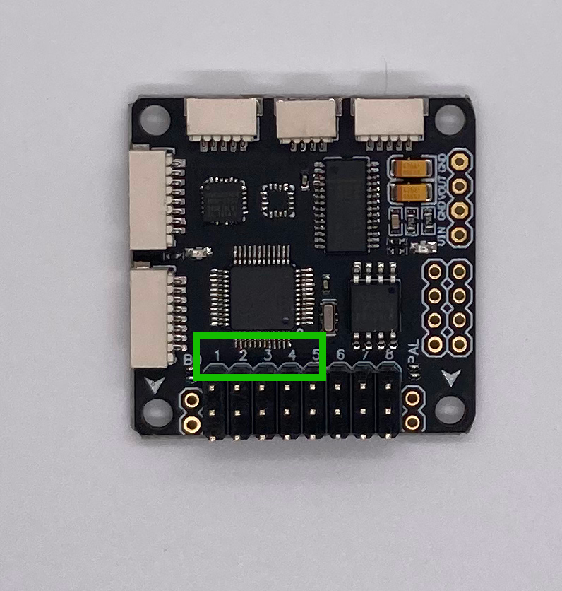
Fig. 86 Motors numbering on the Flight Controller#
For example, in the image below, motor 1 is in the bottom right; therefore you will take the PWM wire from the ESC connected to the motor in the bottom right of your drone, and connect this to the pins labeled 1 on the flight controller.
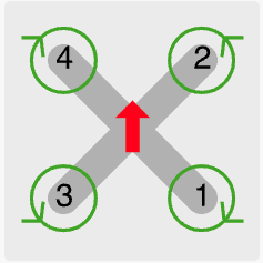
Fig. 87 Motors numbering#
Attention
There is a correct way to connect an ESC cable to the Flight Controller.
See below on how to connect your Flight Controller version to the ESCs.
Make sure the white wire of the ESC signal wire pair is facing in from the board, and the black wire is facing out.
Make sure the white wire of the ESC signal wire pair is connected to the top pins, and the black wire is connected to the bottom pins.
Testing the Motors#
With the ESCs connected to the Flight Controller, your drone’s motors can be tested. In this section, you will verify that the motors are spinning correctly.
Danger
Make sure no propellers are attached to your drone’s motors!
You will be spinning the motors and you don’t want your drone to fly off your desk!
Launch Cleanflight Configurator#
Open up Cleanflight Configurator on your base station.
Connect your drone#
Plug your drone’s Flight Controller into your base station (via the USB to micro USB cable)
Press
"Connect"in the top right corner of Cleanflight. (You won’t need to do this if"autoconnect"was selected)Plug the battery into your drone.
Test each motor#
Slowly spin up the first motor by slowly dragging the 1 slider up
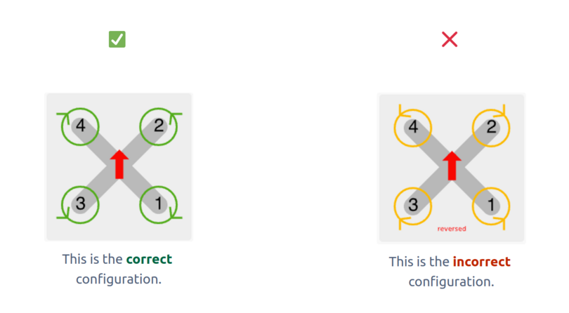
Use the motors diagram to verify that:
the correct motor spins. If the correct motor does not spin, reconnect the ESC wires to the Flight Controller in the correct order.
the motor spins in the correct direction. If the motor spins in the incorrect direction, take note and you will correct it later on.
Tip
One way to find out which direction the motor is spinning is to put a piece of tape on the motor to create a flap. Then, use a pencil or other object and touch it to the tape while the motor is spinning to see which direction it is pushed.
Attention
DO NOT follow the incorrect motors diagram. If Cleanflight shows the incorrect motors diagram, then ignore it - the diagram is a UI bug and does not affect the spin directions of the motors.
Repeat this process for all the motors.
Change the Motor Directions#
Warning
Power your drone off by disconnecting the power supply.
For each motor that is spinning in the incorrect direction:
Disconnect any 2 of the 3 ESC wires from the motor. Keep track of which wires used to be connected together.
Swap the connections of the two wires.
Verify#
Re-connect a power supply to your drone and check that the motors are now spinning in the correct direction. If not, repeat the swapping process.
Calibrate the ESCs#
By this point, your drone’s Flight Controller should be able to spin up each of the 4 motors. This is possible because the Flight Controller is sending PWM signals to each of the 4 ESCs, which in turn sends electrical signals to each of the 4 motors.
A PWM signal is a signal that communicates at how much RPM an ESC should spin a motor. For example, the PWM signal “1000” might correspond to 2300 RPM.
However, note that your drone has not 1, but 4 ESCs - which may not all have the same PWM-to-RPM understanding. For example, ESC 1 might think the PWM signal “1100” from the Flight Controller means 2300 RPM while ESC 2 might think the PWM signal “1000” means 2300 RPM.
The solution to this problem is to calibrate the ESCs with the Flight Controller. In this context, calibration means getting all the ESCs to have the same PWM-to-RPM understanding from the Flight Controller. In this section, you will calibrate your ESCs.
Symptoms of no calibration
scorching hot motors
a drone that lifts to one side during flight
motors that appear to spin at different speeds.
Duckiecaptain might become endangered
Disconnect Power#
Unplug the battery from your drone.
Danger
Make sure no propellers are attached to your drone’s motors!
Launch Cleanflight#
On your base station, open cleanflight
Connect the Flight Controller to a computer and click “Connect” in the top right of the screen
Navigate to Motors tab#
Go to the Motors tab in Cleanflight.
Read the safety notice and check the box that says
“I understand the risks, propellers are removed - Enable motor control”.
Calibrate#
With the battery disconnected, drag the master slider up to
full. All 4 motor sliders should automatically move up to full accordingly (e.g.2000).Plug the battery into your drone.
The ESCs will make an interesting set of sounds, kind of like music. If they do not, stop and try the previous steps again.
After the music stops, drag the master slider to the bottom of the bar. Correspondingly, all 4 motor sliders should automatically be at the bottoms of their bars (e.g.
1000). The motors will make another set of sounds.After the sounds stop, spin up each motor and verify it is spinning in the correct direction (i.e. according to the motors diagram in this doc).