Overview
Contents
Overview#
In this phase of the build, you will attach the Flight Controller to your drone and to the ESCs.
You have already configured the Flight Controller software, now you will use it to test and calibrate ESCs.
Flight Controller#
Warning
Two different versions of Flight Controllers are shipped depending on supplies.
Make sure to check which version you have and follow the appropriate instructions by selecting the correct tab when needed.
Check this section if you’re not sure which version you have.
What you will need
Flight Controller
USB to Micro USB cable
Nylon M3 white bolts and nuts
M3 Rubber spacers
Base station
What you will get
Working Flight Controller stack.
Flight Controller#
The Flight Controller (i.e. Flight Controller) contains multiple sensors: an Inertial Measurement Unit (IMU) and a gyroscope. The IMU measures linear accelerations and the gyroscope measures angular velocities. The Flight Controller also receives commands from the Raspberry Pi and then sends electrical signals to the ESCs which in turn change the speeds of the motors.
Attention
You should already have installed the correct version of Cleanflight on your Flight Controller.
See also
If you haven’t or you’re not sure you can reflash the Flight Controller following the Flight Controller initialization instructions here.
The Flight Controller bag will also contain header pins to be soldered and connectors. These differ between the two Flight Controller versions, use the tabs below to select yours.
In the Flight Controller bag you’ll also find:
1 set of 8x3 straight pins
1 set of 2x4 straight pins
1 strip of straight pins
1 strip of 90 degrees pins
Cabling
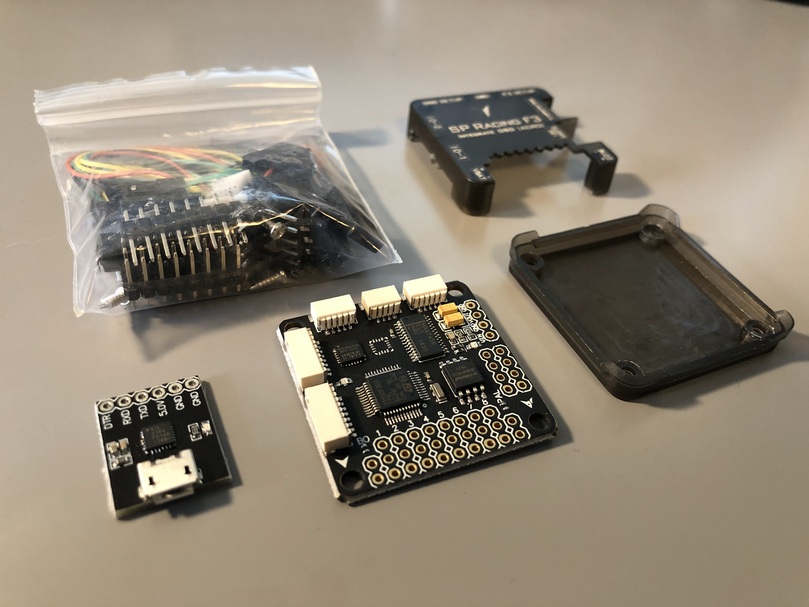
Fig. 72 OSD Flight Controller#
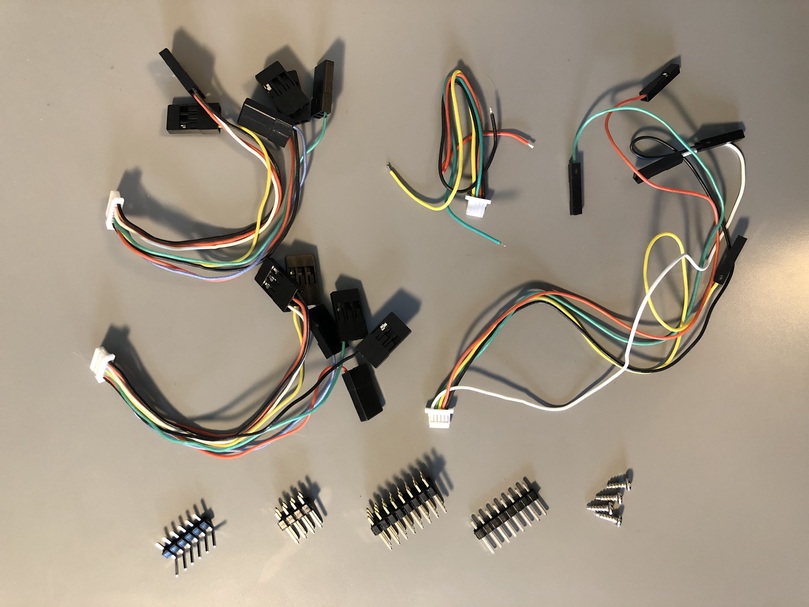
Fig. 73 Cabling included with OSD Flight Controller#
In the Flight Controller bag you’ll also find:
1 set of 8x3 straight pins
1 set of 8x3 bent 90° pins
1 strip of straight pins
Cabling
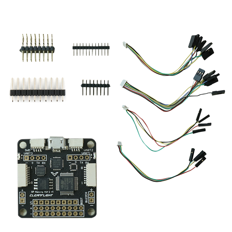
Fig. 74 ACRO Flight Controller#
Note
Due to packaging variations there might be a slightly different number of straight pins or you might find only 8x3 straight pins rather than 90° bent pins.
This is okay, you should anyways get the needed pins to have the functionality required by your Duckiedrone.
USB to Micro USB cable#
This cable is used for two purposes:
To configure the Flight Controller settings in CleanFlight
Note
This part only needs to be done once.
To send the flight commands from the Raspberry Pi to the Flight Controller. This connection allows our software on the Raspberry Pi to control the motors. The Raspberry Pi tells the Flight Controller what roll, pitch, yaw, and throttle values the drone should have, and then the Flight Controller speeds up or slows down the motors to achieve these values.
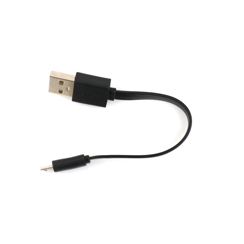
Fig. 75 Micro USB cable#
Rubber spacers#
These spacers are used to isolate the Flight Controller and dampen the vibrations from the ESCs, to improve accuracy in the accelerometer readings.
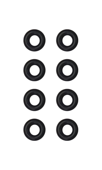
Fig. 76 M3 Rubber spacers#
Nylon M3 bolts and nuts#
These plastic bolts are used to attach the PDB to the frame of the Duckiedrone.
Warning
You will find both M3 and M2 bolts and nuts in your Duckiebox, pay attention to use the M3 in this section.
You can distinguish them by:
comparing the two; the M3 bolts will be slightly thicker
the M2 bolts only have 4 corresponding nuts
the M3 bolts have 11 corresponding nuts
The M3 bolts will fit firmly in the PDB mounting holes, whereas the M2 bolts would wobble and be loose.
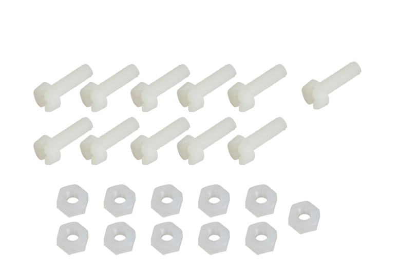
Fig. 77 Nylon M3 bolts (8) and nuts (11)#
Identifying your Flight Controller board#
Attention
There are currently 2 types of Flight Controller hardware.
Identify here which type of Flight Controller you have and use the steps corresponding to your hardware.
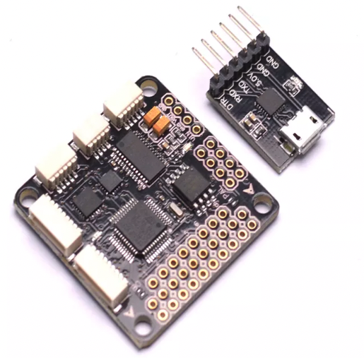
Fig. 78 OSD version Flight Controller#
There is no micro USB port on the Flight Controller (it is on a separate smaller board)
As highlighted below, the Boot pins are exposed near the
BOmarking.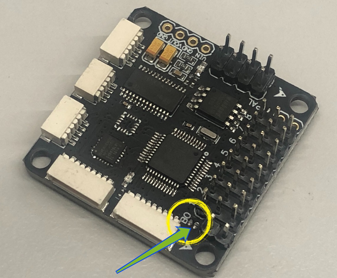
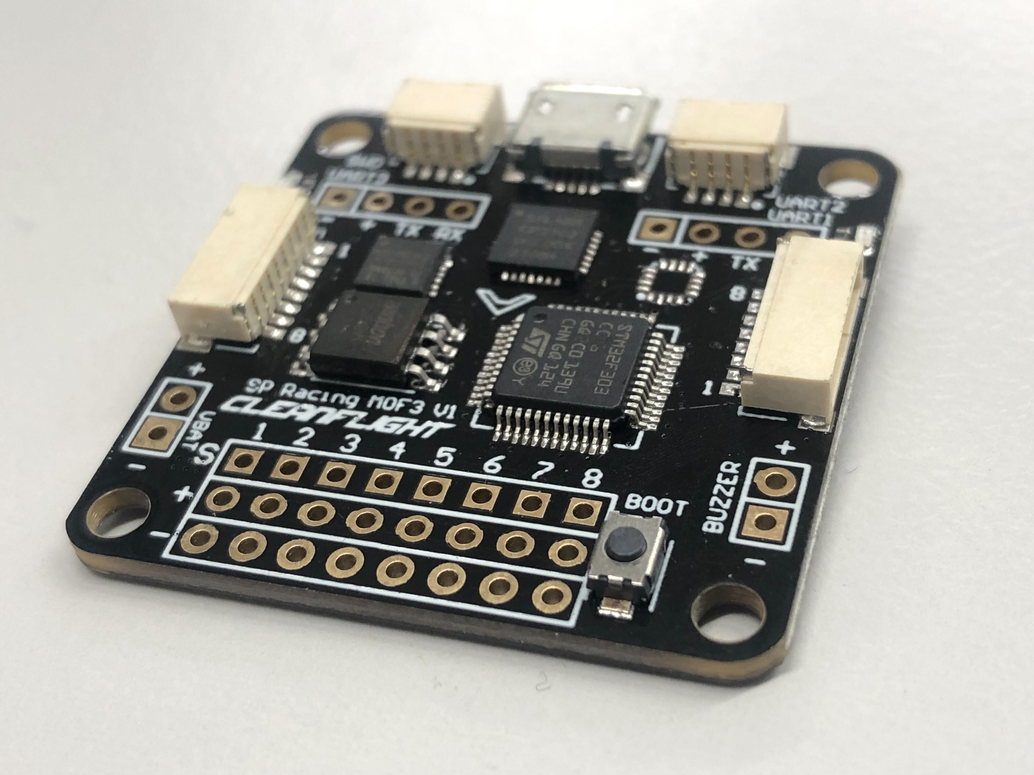
Fig. 79 ACRO version Flight Controller#
There is a micro USB port soldered on the board
There is a
BOOTpush button