Instructions
Contents
Instructions#
Expected Time
3 hours
Preliminary Tasks#
Charge the Battery#
Start charging your drone battery so it is ready when you need it. To charge the battery connect it to the 3 Cells plug of the charger and connect it to the charging adapter.
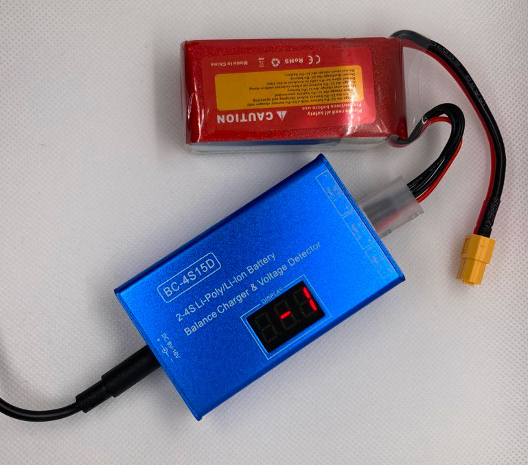
Fig. 37 Battery connected to the charger (the display will show different codes)#
The battery takes about 2 hours to charge. When charging, the battery flashes between the voltage on each cell and "ALL", the voltage on all cells together.
Warning
The battery is fully charged when "ALL" is 12.6 volts.
The charger will also start emitting a BEEP sound when charging is complete.
Disconnect your battery.
You can also tell by measuring the voltage across the battery’s power and ground with a multimeter. When the battery is plugged into a charger and the charger is not plugged into a wall, it uses power from the battery to display the voltage on the battery. Over time this will drain the battery. If a battery’s voltage gets too low, the battery can then no longer be charged.
Warning
Never leave a charging battery unattended, and always unplug the battery as soon as it is charged.
Attach the pin Header to the Raspberry Pi Hat#
Identify the front and back#
Identify the side of the Raspberry Pi Hat that has writing on it - this side is the front, and the side without writing is the back.
Tip
Take note of where the slot in the Raspberry Pi Hat is to help with matching the orientation in the following instructions.
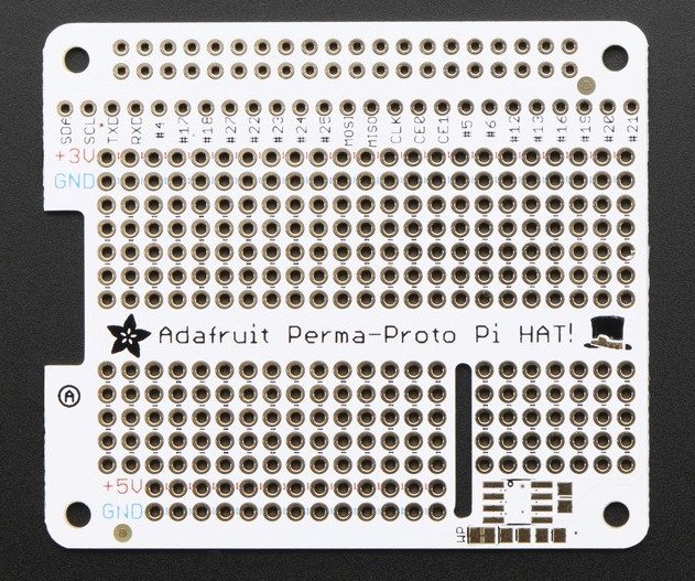
Fig. 38 Raspberry Pi Hat front#
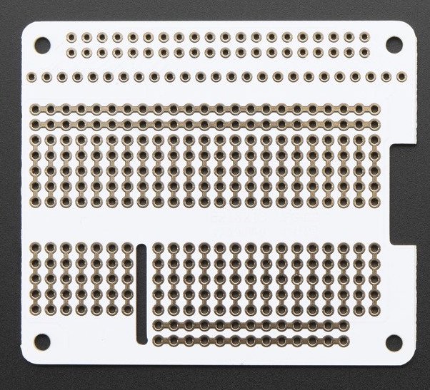
Fig. 39 Raspberry Pi Hat back#
1 - Insert the Pin Header#
Insert the Pin Header into the back of the Raspberry Pi Hat as shown in the image (the black plastic side will be on the side without any writing).
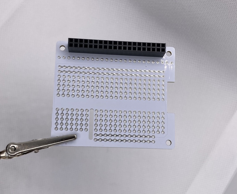
Fig. 40 Pin header inserted into the back of Raspberry Pi Hat#
2 - Solder the Pin Header#
Attention
Review the through-hole soldering technique
Use the helping hands to assist as you solder the pin header
Note
It’s very easy to add too much solder and create a solder bridge between adjacent pins. Visually inspect your soldering to make sure that adjacent pins are not connected by globs of solder.
Good soldering:
Attention
Bad soldering:
If you have a solder bridge, try the technique shown in this video. If this does not work, you can use a desoldering wick or a solder sucker to remove the excess solder.
Check
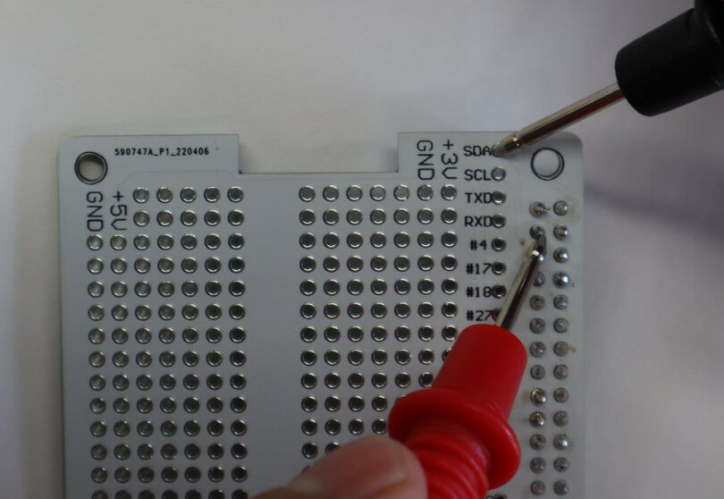
Sometime too much heat when soldering the pin header can mess up the Raspberry Pi Hat connections. To make sure the connections are still good, do a connectivity check on the Raspberry Pi Hat. Verify there is:
A short between the hole labelled
SDAon the Raspberry Pi Hat and the pin at row 2 column 1 of the pin header that you soldered.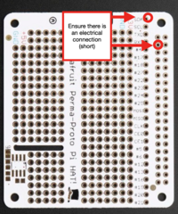
A short between the hole labelled
SCLon the Raspberry Pi Hat and the pin at row 3 column 1 of the pin header that you soldered.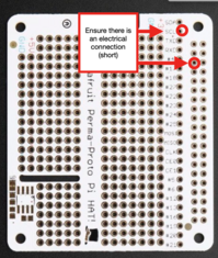
Tip
Use the multimeter to check for connections:
Attach the UBEC to the Raspberry Pi Hat#
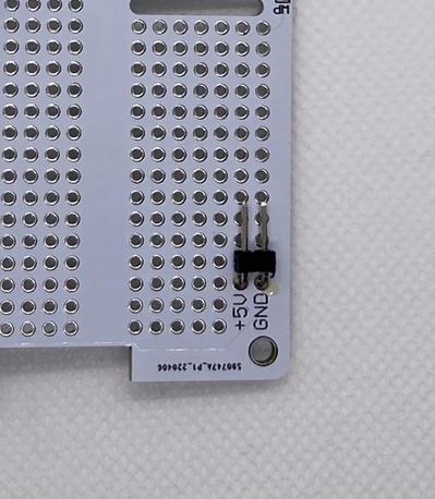
The UBEC is a battery eliminator circuit that lowers the voltage from the battery from 12V (used by the motors) to 5V (used by the Pi). We will power the Pi by connecting it to the battery via the UBEC. Within your kit you are provided with a few 90 degrees header pins.
You will need to solder one of them (with two pins) into the +5V and GND rails as shown.
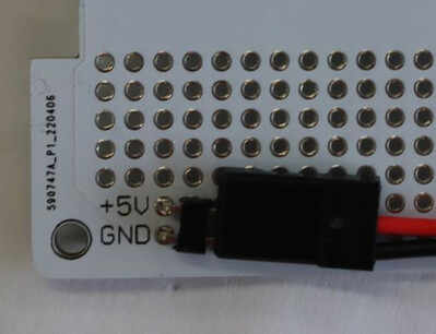
The UBEC comes with a black connector which you can plug into your newly soldered pins.
While you could directly solder the UBEC to the Raspberry Pi Hat, using the pins provides a plug and play feature when needing to disassemble the drone. Also allowing the user to test motors while not having the Raspberry Pi drain power from them.
Attention
Make sure to plug in the conector correctly with red wire on +5V and black wire respectively on GND. Leaving the last pin hole on the UBEC connector free.
Attention
Do a connectivity check on the Raspberry Pi Hat.
Verify there is
no short between the +5V rail and the GND rail on the Raspberry Pi Hat
Attaching Wi-Fi mode pins#
The Raspberry Pi has a unique way to understand how to switch between its two different Wi-Fi modes.
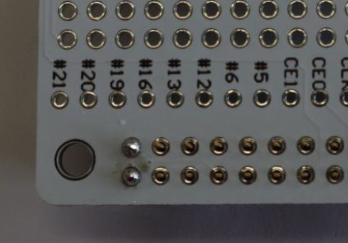
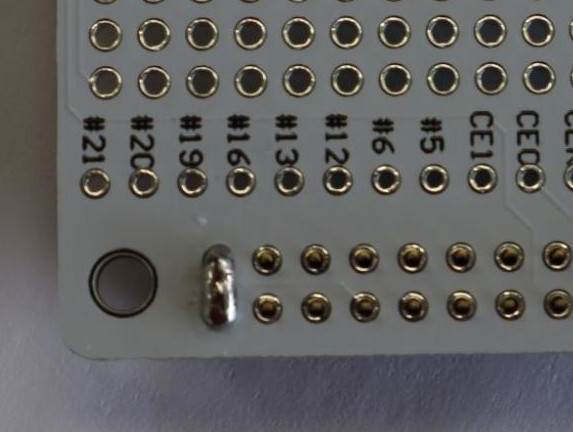
You will be soldering another set of 90 degree pins in port #5 and port #6 of the Raspberry Pi Hat as shown in the following image.
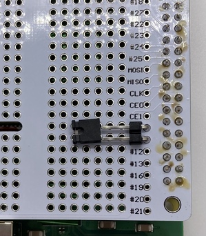
Fig. 41 WiFi mode pins with jumper (not inserted in the pic)#
Attention
The other piece of hardware shown in the image, which is a black cap-like device next to the soldered pins, is a jumper to short the pins. This piece is very small, be careful not to lose this.
It is advised to insert it into the pins for safe keeping.
Warning
Remember that it does matter whether the jumper is plugged into both pins or just one when booting your Raspberry Pi up:
Jumper plugged in both pins → access point mode
Jumper plugged in only one pin → client mode
Preparing the PDB#
The PDB (Power distribution board) takes power from the battery and distributes it to the motors (at 12V) and to the Raspberry Pi (via the BEC which converts it to 5V). Note that the PDB itself includes a separate BEC, but in our testing we found it did not provide enough amps to power the Pi, so we provide an external UBEC.
Tin the PDB#
Similar to exposed wires, the metal pads on a PDB need to be tinned. This will allow tinned wires to be joined to the pads - and therefore the PDB.
Warning
It is very important to use a chisel tip soldering iron rather than the pointed tip you used for soldering the header to the Raspberry Pi Hat.
Make sure to unplug your soldering iron and let it cool down completely before switching the tip.
This tip applies more heat quickly to the pad, so that the solder flows onto the pad when you tin it.
Tin every pad on the PDB, including the GND 12V pads.
Warning
Be careful not to aggressively push the soldering iron tip into the PDB, as too much force will cut the pads right off.
Here’s a video of the process.
Note
For the remainder of the instructions, unless stated otherwise, red wires should be soldered to positive (+) pads and black wires should be soldered to ground (-) pads.
Solder the XT60 Battery Connector to the PDB#
Cut the metal-covered ends off of the battery connector wires
Strip the ends of the battery connector wires so that about 1 cm of wire is exposed
Tin the exposed ends of the XT60 connector (The original tinning is harder to connect to than freshly-tinned ends)
Solder the XT60 red (
+) wire to the tinned positive (+) opening on the PDB, and solder the black (-) wire to the tinned ground (-) opening on the PDB.
Tip
This wire is very thick and it will take a while for the solder to melt.
Make sure your soldering iron is turned all the way up, you’re using a chisel tip and be patient.
It also helps to keep the cable at an angle to have it touch the copper hole while soldering.
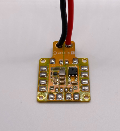
Fig. 42 Tinned PDB with XT60 soldered#
Solder the UBEC to the PDB#
Tin the ends of the red and black wires that are connected to the side of the UBEC labeled INPUT (they’re pre-tinned, you should cut the cable and tin it again).
Solder the BEC red (+) INPUT wire to the positive (+) pad on the PDB 12V pad, and solder the black (-) INPUT wire to the GND pad on the PDB, as shown in the image.
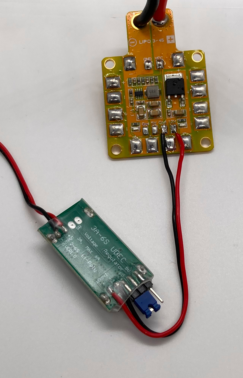
Fig. 43 UBEC soldered to PDB#
Check
Visually inspect the drone to verify the following:
All red wires connected to the PDB are connected to positive (
+) padsAll black wires connected to the PDB are connected to negative (
-) padsThe wires on the
INPUTside - NOT theOUTPUTside - of the BEC are soldered to the PDB.
Check
Do a connectivity check on the PDB.
Verify there is:
a short between any positive (
+) pad and any other positive (+) pada short between any negative (
-) pad and any other negative (-) padno short between any positive (
+) pad and any negative (-) pad
Check
only if the connectivity check passed, do a DC voltage check on the PDB.
Plug in a 12V battery and verify there is:
~0V between any positive (
+) pad and any other positive (+) pad~0V between any negative (
-) pad and any other negative (-) pad~12V between any positive (
+) pad and any negative (-) pad.
Note
If the battery is charged to X volts instead of 12 volts (e.g. 10), then the multimeter will show X volts instead of 12 volts.
Check
only if the DC voltage check passed, re-connect a battery to your drone and verify the following:
red LEDs on the PDB light up.
red LED on Raspberry Pi lights up.
Put Heat Sinks on Raspberry Pi#
Attach the heat sinks to the Raspberry Pi as shown in the pictures.
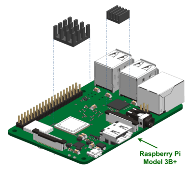
Fig. 44 Top heatsinks#
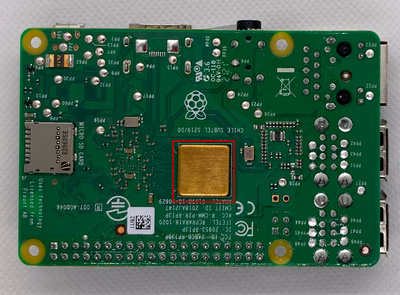
Fig. 45 Bottom heatsink#
Attach the Raspberry Pi Hat to the Raspberry Pi#
Align the 2x40 GPIO pins on the Raspberry Pi with the 2x40 pin header that you soldered to the Raspberry Pi Hat as shown in the image.
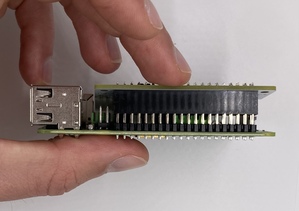
Fig. 46 Raspberry Pi Hat lined up with Raspberry Pi pins#
Press the pin header down onto the GPIO pins to connect the Raspberry Pi Hat.
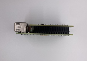
Fig. 47 Raspberry Pi Hat inserted into Raspberry Pi pins#
Final Steps#
Check
On the Raspberry Pi Hat, do another connectivity check to verify that there is no short between the +5V rail and the GND rail.
Verify that the Raspberry Pi has power:
Connect the battery
Verify that the BEC has a solid red light.
Verify that the Raspberry Pi has a solid red light.
Insert the SD card into the Pi#
Disconnect the UBEC from the Raspberry Pi Hat
You will boot the Raspberry Pi once the build is complete, for now on until the first boot make sure the Raspberry Pi isn’t powered.
Insert your (previously flashed) micro SD card into the micro SD card slot on the bottom of the Pi.
Attention
The micro SD card direction does matter - the lettering on the SD card should be facing away from the Pi.
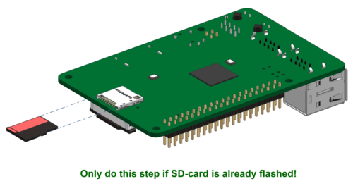
Fig. 48 Micro SD Card being inserted into the Raspberry Pi#