Instructions
Contents
Instructions#
Attach the standoffs to the bottom frame#
Attach the 4 long nylon white standoffs to the bottom of the frame by screwing them with M2 nylon screws on the back of the bottom frame, as shown in the image.
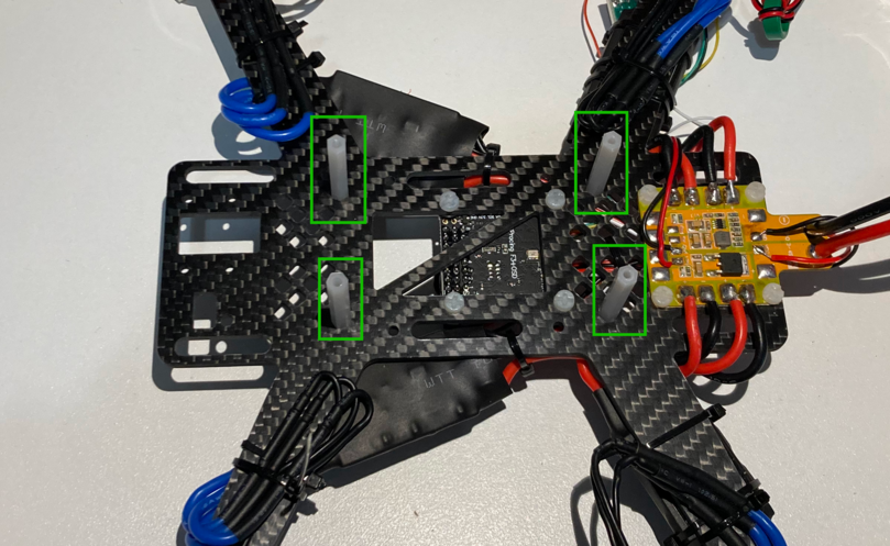
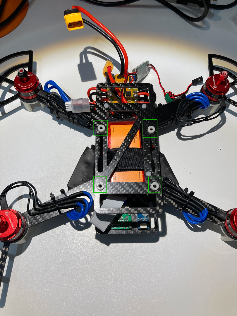
Fig. 95 Nylon standoffs mounted on bottom frame#
Secure the battery to the frame#
Place the battery in between the nylon standoffs and secure it to the frame by using one zip tie and a Velcro strap.
Tip
To allow the battery to be hot-swapped easily after a flight it is suggested to attach the velcro strap such that you can open it from the bottom side of the drone.
Attention
Make sure to secure the battery tightly to the frame to avoid it moving during flight.
Tip
You can use the holes in the rear part of the frame (towards the PDB) to attach the battery cables using a zip ties.
Keep this zip tie loose to allow swapping out the battery quickly.
This minimizes the sideways wobbling of the battery.
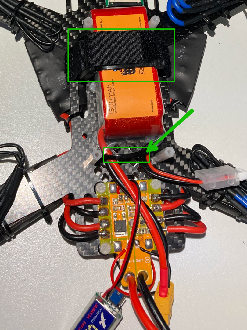
Fig. 96 Battery secured to the frame using zip ties and velcro strap#
Attach the ToF sensor#
Attention
There’s a tiny piece of yellow tape on the black tab, make sure to remove it before attaching it to the drone
Place the ToF sensor on the smaller left hole, making sure to align it so that the small black chip is looking down through the hole.
Using one M3 nylon bolt and nut, screw the ToF sensor to the frame.
Attach the Raspberry Pi Camera to the drone frame#
The Raspberry Pi Camera has to be secured to the frame.
Attention
The Raspberry Pi Camera has tape on the back of the black lens assembly that has to be fixed to the PCB before mounting it on the frame
Peel off the tape on the back side of the lens assembly of the Raspberry Pi Camera and attach it to the PCB
Make sure the flex connector (called FFC) from the lens assembly is attached to its connector.
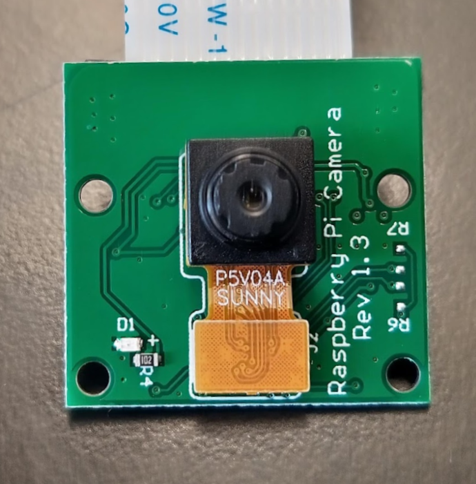
Fig. 97 Camera with lens assembly attached and connected#
Screw the Raspberry Pi Camera to the right hole in the front part of the drone using the small nylon bolts and nuts. Attach on top, so that the camera faces downward and the FFC goes towards the drone’s battery.
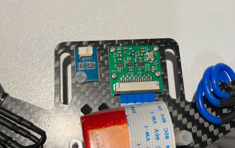
Fig. 98 Camera (and ToF sensor) attached to the front of the frame#
Warning
Do not use the metal M2 screws as they might short the PCB.
Only use them if you have an old hardware revision, see Troubleshooting if you have power issues.
Mount the top frame#
Identify the smaller black rectangular laser cut piece of the frame.
Attach the large nylon spacers through the small screw holes using four M2 nylon screws.
Attention
Make sure the upper frame is oriented in the correct direction, as shown in the figure.
There is a larger rectangular opening in it that shall be oriented towards the back of the drone.
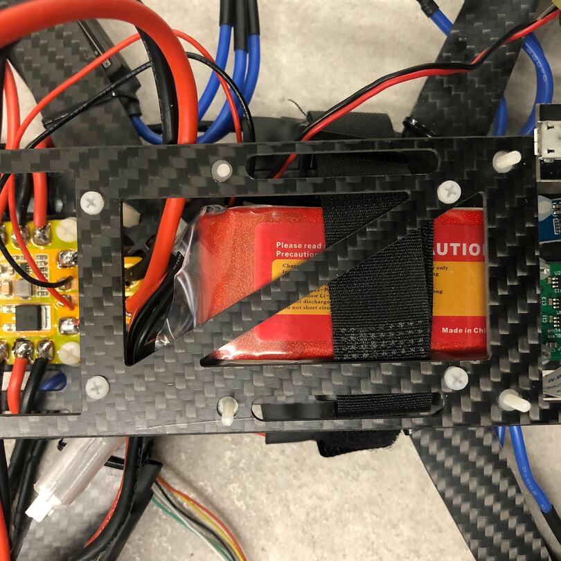
Fig. 99 Top frame mounted on the standoffs (ignore the bolts protruding)#
Tip
You might need to slightly squeeze the nylon standoffs together due to the battery being in between them.
This is okay, and it has also the benefit of further securing the battery to the frame
Mount the Raspberry Pi#
Now you are going to attach the Raspberry Pi to the top of the frame using zip ties.
Identify the 4 holes on the top frame and place nylon spacers on each
Place the Raspberry Pi on top, taking care not to move the spacers
Mount the Raspberry Pi on top using the 4 M2.5 nylon screws: insert them from the bottom and screw them in the short M2.5 spacers.
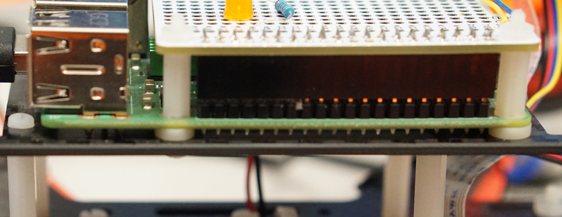
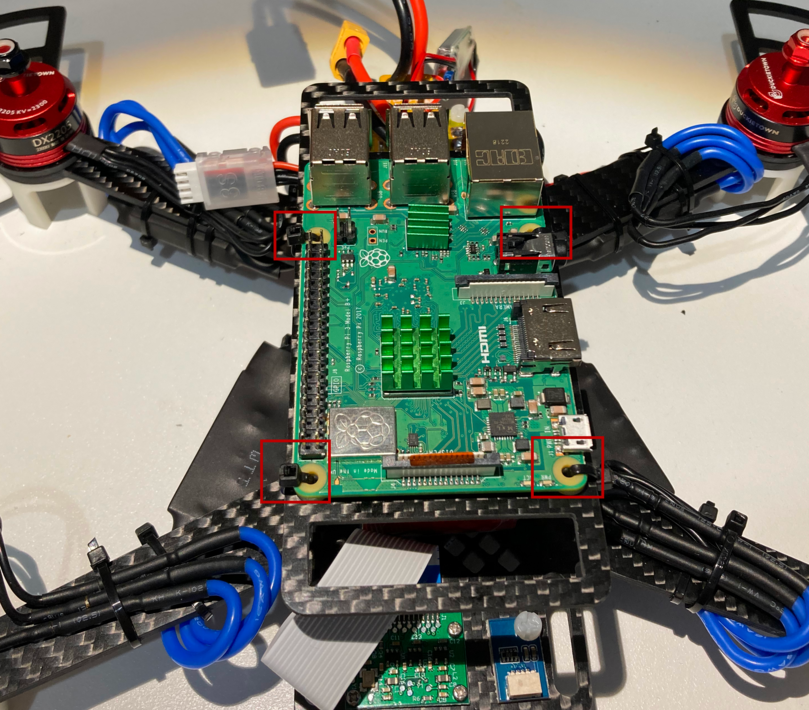
Fig. 100 Raspberry Pi mounted on the upper frame (with Raspberry Pi Hat)#
Note
Some old hardware revisions did not have enough M2.5 nylon screws. If this is the case you can use 4 small zip ties to secure the Raspberry Pi in place.
Connect the camera and attach the Raspberry Pi Hat#
You will now connect the camera to the Raspberry Pi and attach the Raspberry Pi Hat.
Attention
The camera connector cable (called FFC) has to go through the opening of the Raspberry Pi Hat before this is attached to the Raspberry Pi in order to be able to connect it to the Raspberry Pi.
Feed the FFC cable through the opening of the Raspberry Pi Hat as shown in the picture.
Note
Make sure that the Raspberry Pi Hat is oriented with the pins facing up and on the same side as the pins of the Raspberry Pi, and that the blue tape is facing up as in the figure.
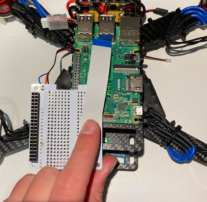
Fig. 101 Raspberry Pi Camera flex cable going through the Raspberry Pi Hat#
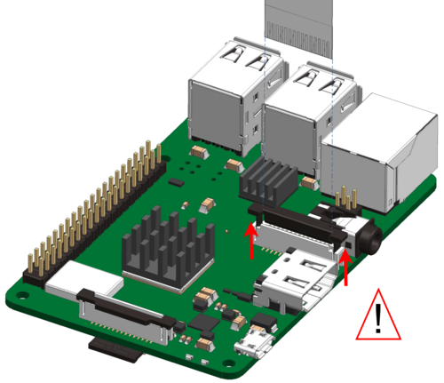
Fig. 102 Lift the camera connector plastic flap.#
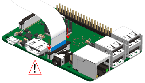
Fig. 103 Insert the camera cable in the connector with the blue side facing towards the Ethernet port and close the plastic flap.#
See also
Watch this video to understand how to attach the connector properly
Attach the Raspberry Pi Hat to the GPIO pins of the Raspberry Pi being careful when handling the flexible camera cable.
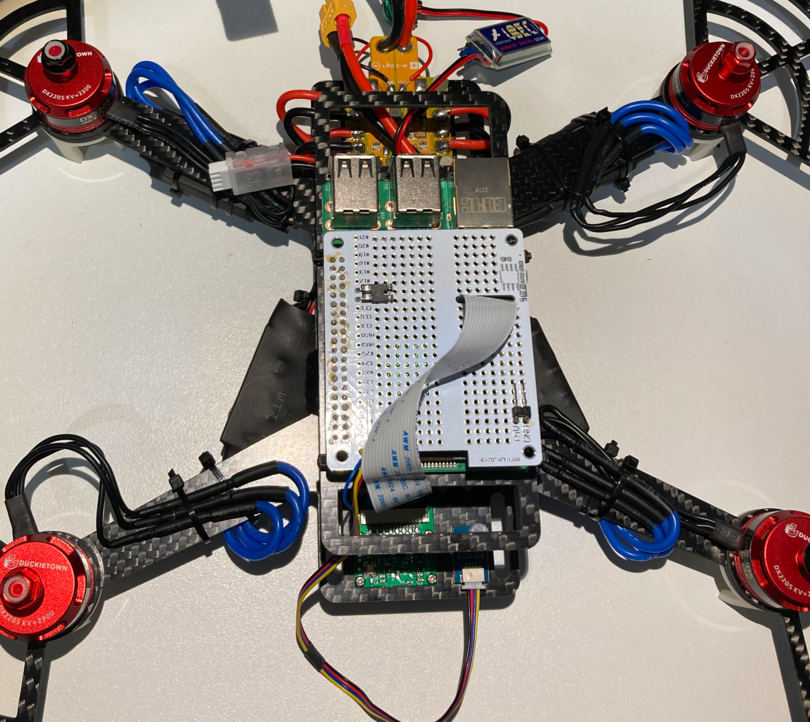
Fig. 104 Raspberry Pi Hat connected to the Raspberry Raspberry Pi with the camera cable routed through its opening#
Attach the UBEC#
Use a piece of foam double-sided tape to attach the UBEC to the top of the USB ports of the Raspberry Pi as shown.
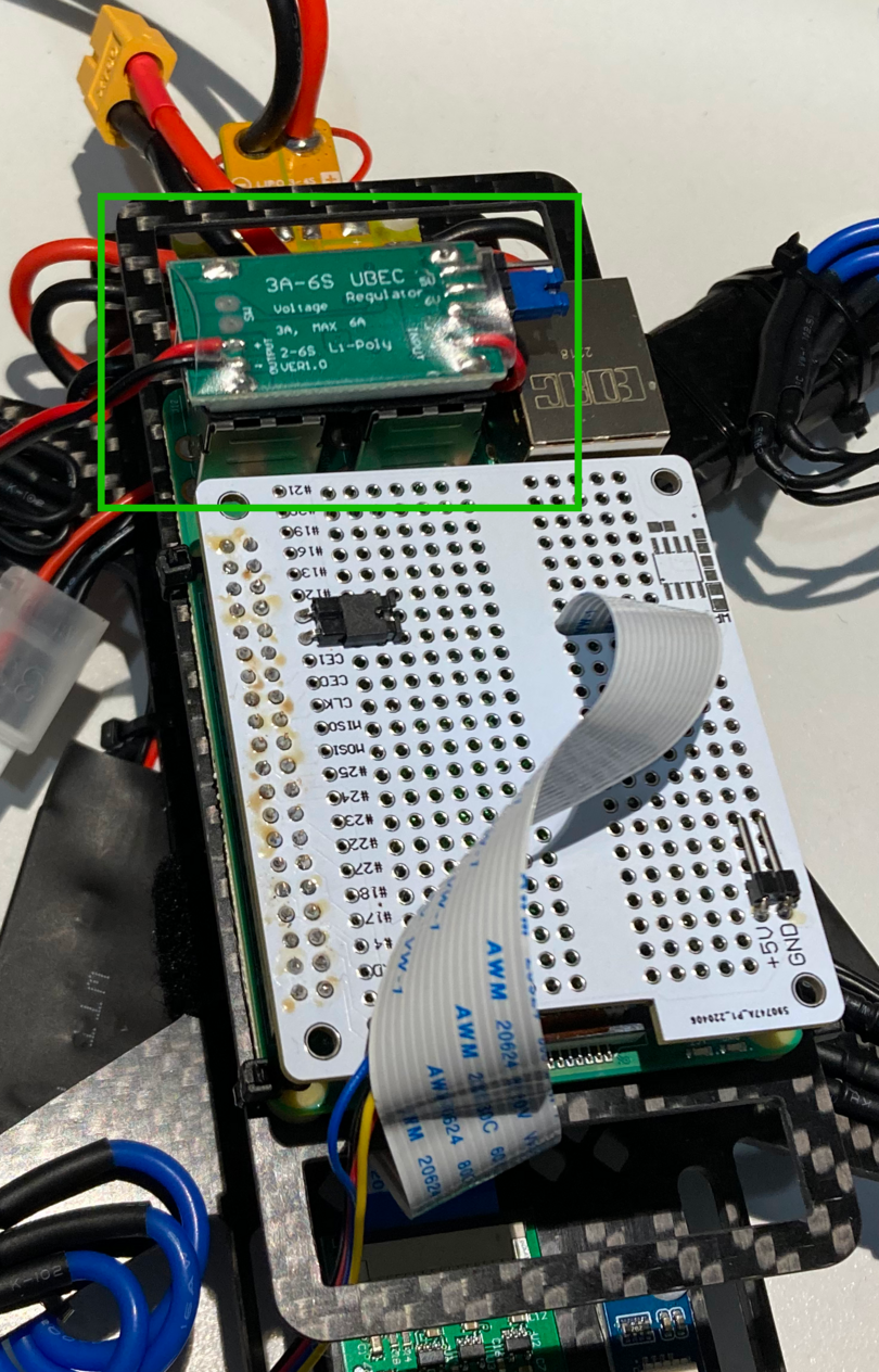
Fig. 105 UBEC attached to the Raspberry Pi USB ports#
Connect sensors and UBEC#
Connect the UBEC to the pins soldered on the
5VandGNDrailsDanger
Be careful to not connect the UBEC to the WiFi mode selection pins as doing so will damage your Raspberry Pi
Attach the soldered ToF cable from the Raspberry Pi Hat to the ToF sensor.
Connect the Flight Controller USB cable to one of the USB ports on the Raspberry Pi
Note
If you have the OSD version of the Flight Controller, you can use a piece of double sided foam tape to attach the USB connector board to the frame, right beneath the PDB board.
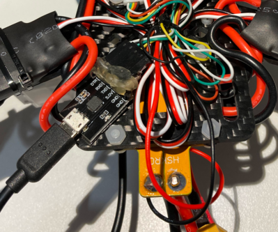
Fig. 106 USB board attached to the frame (OSD Flight Controller)#
Angle it so that the USB connector doesn’t protrude much, otherwise you might encounter clearance issues with the propellers.
Fix cables to the frame#
Make sure to attach all dangling cables using zip ties to the frame, such that no wires can hit the propellers.
Attention
Fix the cables to allow the drone to lie flat on the ground. This is important to calibrate the Flight Controller.
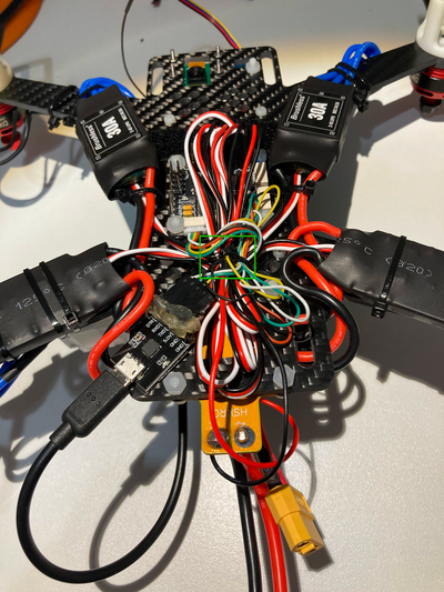
Fig. 107 PWM wires fixed to the bottom of the frame (zip tie in the center)#
Danger
Make sure ESC-motor wires are ziptied down properly. If not, you risk having a short.
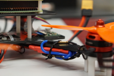
Fig. 108 Properly tied ESCs cables#
Attach propellers#
Attach the propellers to the drone so that it may fly: attach CW propellers to the CW motors, and CCW propellers to the CCW motors.
Attention
The propellers have small arrows on them in the center to indicate which type they are.
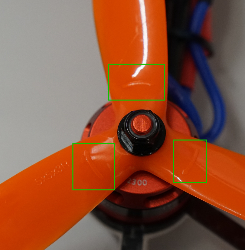
Fig. 109 Arrows on the propellers indicating spin direction#
Tip
The nuts for the motors that spin CCW tighten when turned CW, and the ones on the motors that spin CW tighten when turned CCW.
Use the 8 mm wrench to tighten the bolts down so that the bottom of the propeller is flat on the top of the motor.
Warning
Screw bolts down tightly, but not so tight that you could not remove the propellers if you had to.
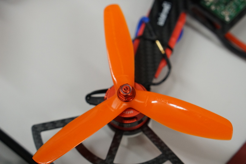
Fig. 110 Propeller attached to the motors#
Battery Monitor#
In your Duckiebox there is one item that we haven’t used so far: the Battery Monitor.
Note
This is optional and not required for flight.
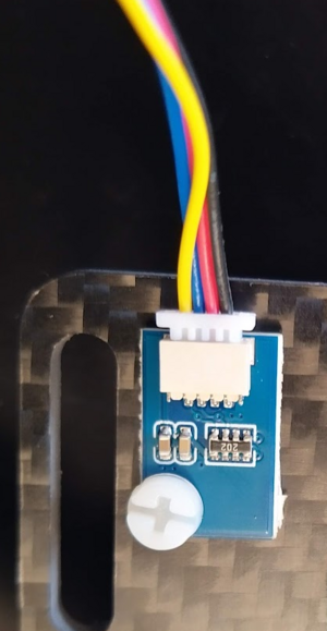
To use this safety device you are going to have to connect it to the 4-pins connector of the LiPo battery, when it is not charging:
Identify the row of pins at the bottom of the Battery Monitor.
Connect the 4-pins connector to the left-most pins, having the first pin connected to the black (
-) wires of the connector.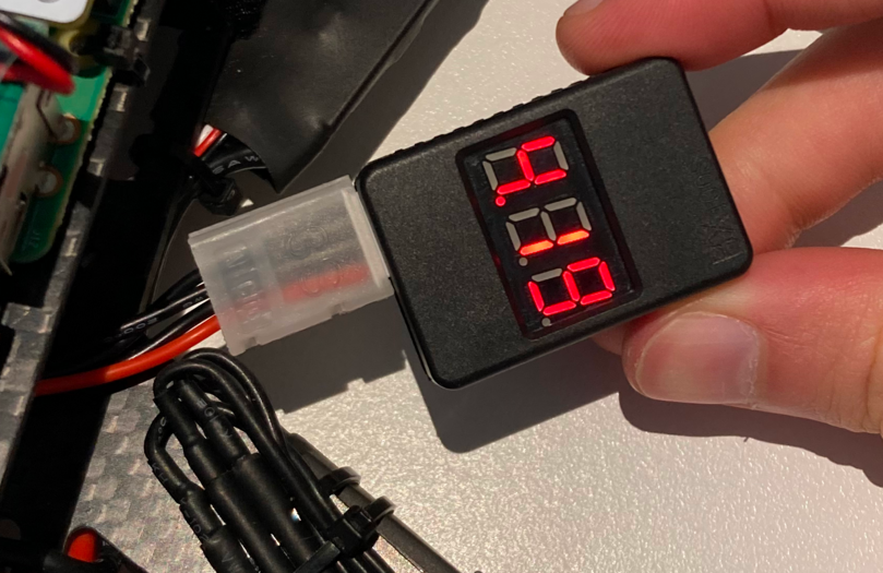
Fig. 111 Battery connected to the Battery Monitor#
Warning
The battery monitor makes a very loud sound when it powers up.
You can cover the speaker holes on the opposide side from the row of pins to protect your ears.
Secure the battery monitor to the chassis of the Duckiedrone.
Note
Due to the length of the battery cable and the limited space on the frame there is not a great mounting spot.
You should pick one making sure that:
The Battery Monitor and battery wire do not interfere with the propellers.
The Battery Monitor will not move during flight.
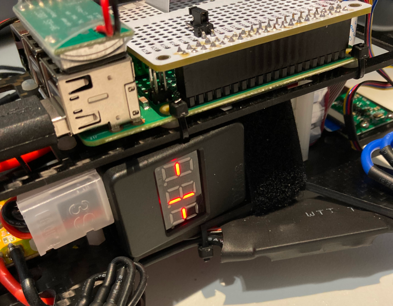
Fig. 112 A possible location to attach the Battery Monitor#
Tip
You can use some double-sided tape to fix the battery monitor.