Instructions
Contents
Instructions#
Note
Sometimes parts will have wires already tinned out-of-the-box by the manufacturer (i.e. pre-tinned).
You can identify this by:
the “shininess” of the tip of a wire and
the inability to fray the wire strands of the tip of a wire.
However, such tinning is often ineffective.
Cut off any pre-tinned tips, then strip and tin the part yourself.
Warning
Visually inspect each ESC and verify that the heat shrinks are on properly; there should be no exposed wires and each heat shrink should be a tight fit.
Do a connectivity check on the XT60 connector cable; verify there is no short between the red and black wire.
Soldering ESCs to the PDB#
An ESC (i.e. Electronic Speed Control) is a component which requires power. It takes this power and provides a variable amount of it to a motor; since a motor’s RPM depends on how much power it gets, an ESC can control how fast a motor spins by controlling how much power it supplies the motor.
Solder each of your 4 ESCs to the PDB, one by one:
Strip about 5 mm of wire from (
+) red and (-) black cables of the ESC.Tin the wire
Solder on the pad, the (
+) red cable solders to the (+) on the PDB and the (-) black cable to the (-) pad.
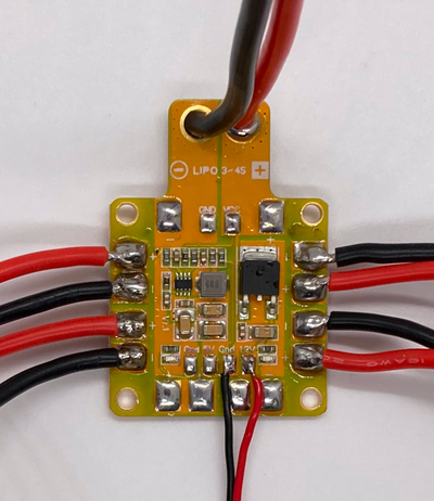
Fig. 62 ESCs cables soldered to the PDB on the side pads.#
Solder battery monitor leads to the PDB#
Solder the 6-inch red and black wires to the PDB to the VCC and GND pads respectively.

Fig. 63 Pads for soldering the red and black monitor battery leads#
These wires are soldered as to go out of the PDB.
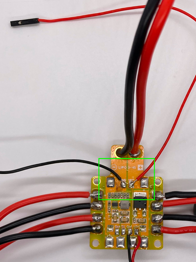
Fig. 64 Battery leads soldered to the PDB#
Warning
It’s important not to strip the wires too much at the PDB end to prevent the positive and negative leads from touching.
Pull very slightly the two wires to make sure they stay connected.
Attaching parts to drone frame#
This section will cover attaching the first set of items to the drone frame.
Attention
Before beginning, verify the PDB is completely soldered with all necessary parts (as covered in previous sections).
For reference, here are the motor directions with respect to the frame:
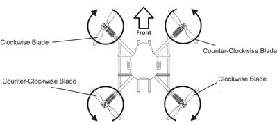
Fig. 65 Your motors MUST spin in these directions#
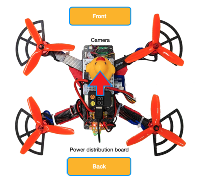
Fig. 66 Notice the colors of the motors nuts in this pic#
(red->counter-clockwise, black->clockwise)
Align the frame#
Place the drone frame on a flat surface so that the back is facing you.
Attach PDB to frame#
Place the completed PDB towards the bottom of the drone frame, with plastic M3 screws in their respective holes. For each of the 4 corner screw holes of the PDB, add a plastic nut on the other end to secure it.
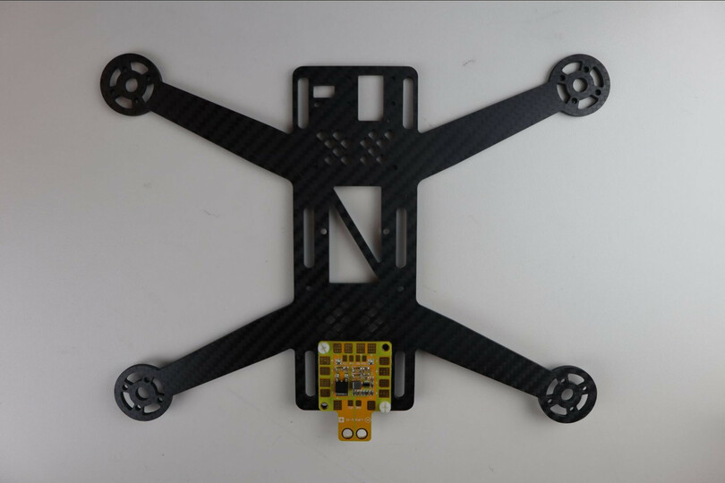
Fig. 67 PDB Secured in Drone Frame (front side up)#
Attach motors#
There are two clockwise and two counter-clockwise motors. Unfortunately the motors themselves are not labeled, so only the color of the nut will let you tell the difference. The clockwise motors have a nut threaded so that when the propellers spin clockwise, the nut will tend to tighten, and the counter-clockwise motors are the opposite.
Attention
The counter-clockwise motors have a red nut.
The clockwise motors have a black nut.
Take the motors out of their bags.
Attention
Immediately screw the nut that came in the bag onto the main bolt sticking out of the motor. Screw the nuts on gently by hand - do not force it.
This will prevent you from mixing up the motors.
Tip
Motors, frame, prop guards and standoffs all have 4 holes each for the screws. These holes are slightly asymmetrical, so that they can only be attached in one direction.
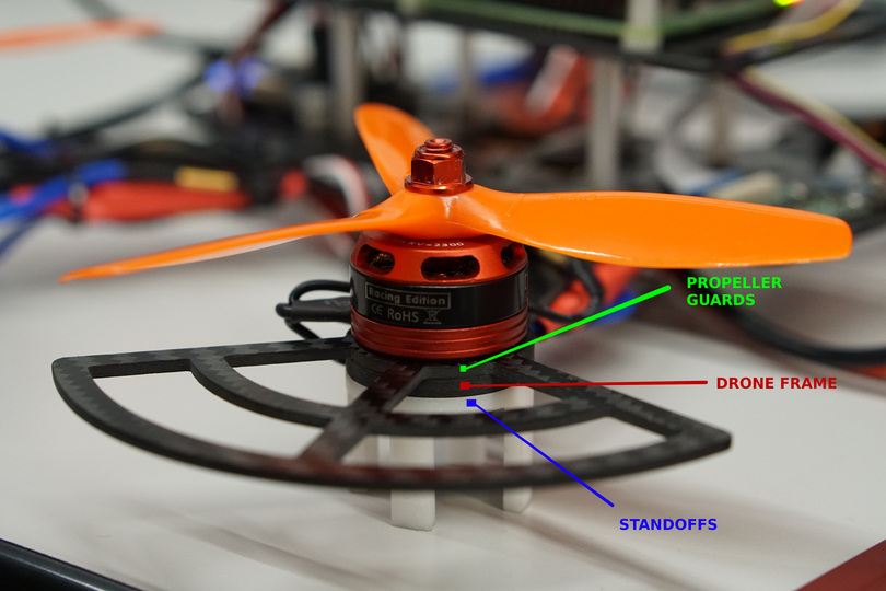
Get the standoffs, insert two screws through the holes and insert them in the holes on the frame (on the back side of the frame).
Get the prop guards, and put a prop guard on the frame. The prop guards will slot underneath each motor, between the motor’s casing and the prop guard.
Attach clockwise motors to the bottom-right and top-left of the drone frame, using 4 long silver M3 screws for each attachment.
Danger
Do not use the black screws that come with the motor
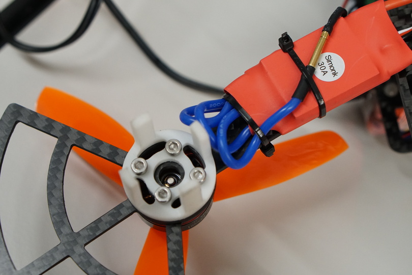
Fig. 69 Motor screwed on the frame with standoffs and prop guards#
notice: the gray M3 screws are used
Attach counter-clockwise motors to the bottom-left and top-right of the drone frame, using 4 long M3 gray screws for each attachment.
Connecting the Motors to the ESCs#
For each motor, connect its plug bullet connectors to the socket bullet connectors of the ESC in the motor’s corner (e.g. top-left motor connects to top-left ESC). Any connection order will suffice for now, as you will be able to change them in a later phase.
Fig. 70 ESCs plugs connected to motors#
Attaching the ESCs to the frame#
Each ESC has to be fixed to the frame. Due to the length of the wires powering the ESCs, you will have to fix the bottom two to the arms and the top two to the arms and the body of the drone, as shown below.
Warning
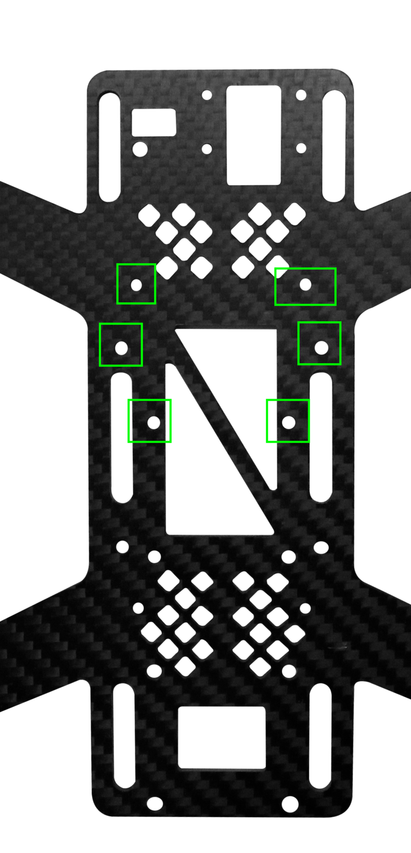
When attaching the top two ESCs to the frame make sure not to cover any of the round holes on the frame of the drone.
They will be used to screw components on later.
Use two thin zip ties provided to fix each ESC, as shown.
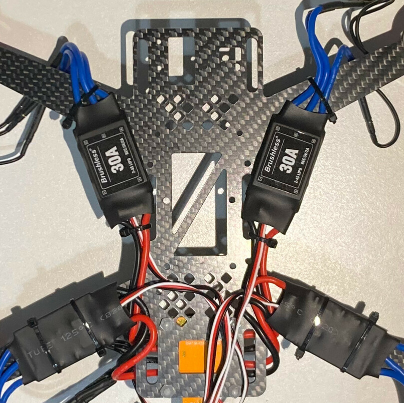
Fig. 71 ESCs attached to the frame#
Attention
Make sure to still be able to connect both the 3-pin wires and the banana-plug wires.
Tip
Fixing first the top two ESCs will allow you to route their cables more easily.
Cut the excess zip ties off to tidy up.