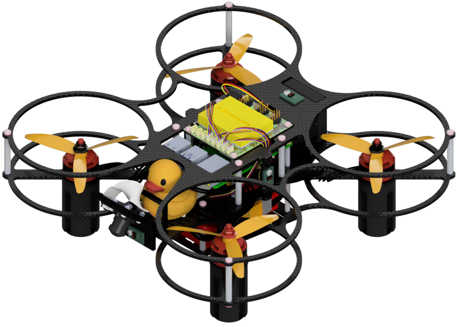
Description of Components (DD24-B)
Contents
Description of Components (DD24-B)#
Most components in the Duckiedrone box are functional, i.e., they serve a purpose in learning to fly, or in flying, the Duckiedrone. Other components are not functional, but still useful, for example the duckies.
We provide below a brief description of each component in the box.
Raspberry Pi 4 - Model B - 4GB#
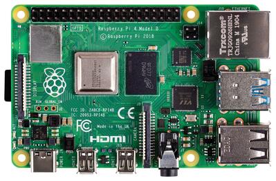
Fig. 10 Raspberry Pi 4 Model B, 4 GB RAM.#
The Raspberry Pi 4 - Model B is a well-known credit card-size computer. This little marvel of technology from Raspberry Pi Ltd. acts as the high-level brain of the Duckiedrone, hosting most of the computation power.
The Duckiedrone DD24-B model uses the Raspberry Pi 4 - Model B, with 4 GB of RAM in its standard configuration. Technical specifications are available on the Raspberry Pi website.
The Duckiedrone is compatible with the Raspberry Pi 5 as well. Both variants are flashed with the same ente image through dts init_sd_card — see Software Initialization.
64GB microSD card - Class 10 U3#
Fig. 11 64 GB Class 10 microSD card.#
The microSD card is the core memory of the Duckiedrone.
While it does look like a regular SD card with 64 GB of nominal capacity, Duckietown microSD cards are “fast”, i.e., they have rather high minimum read and write speeds. Fast communication between the Duckiedrone “brain” (the Raspberry Pi) and memory is needed to prevent lags in the feedback loop.
Note
The microSD card is inserted directly in the Raspberry Pi. Do not use the microSD adapter below during flight.
microSD-to-USB adapter#
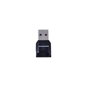
Fig. 12 microSD-to-USB adapter.#
This USB-A microSD adapter is included in the box to support the first initialization of the microSD card.
One of the first steps in the software initialization procedure is to insert the microSD card into the adapter and plug the adapter into your base station (laptop or desktop, not provided in the box) to install the correct software on the Duckiedrone.
Warning
Do not plug the microSD card adapter into the Raspberry Pi during flight. The microSD card goes directly into the Raspberry Pi.
RPi Camera (G) with Fisheye lens and cable#
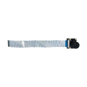
Fig. 13 Raspberry Pi camera with Fisheye lens and cable.#
The camera is an important sensor for Duckiedrone autonomous operations, allowing it to perceive the environment visually.
This is an OV5647 5 MP Raspberry Pi Camera (G) with a 160-degree field of view, thanks to the included fisheye lens, and (manually) adjustable focus distance. The package includes a 30 cm camera cable.
Time-of-Flight (ToF) Sensor#
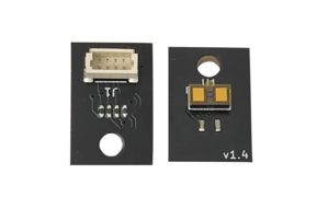
Fig. 14 Time-of-Flight Sensor (back and front).#
Time-of-flight (ToF) sensors are distance measurement sensors. The Duckiedrone mounts five, one on each side and one looking down to measure altitude. The principle of operation is the measurement of the return time of light bouncing off obstacles, so we can think of them as 1D lidars.
The Duckiedrone ToF sensors mount the VL53L1X module (VL53L1X specifications) and come with 15 cm and 23 cm 4-pin JST 1.5 mm cables.
Motors (CCW)#
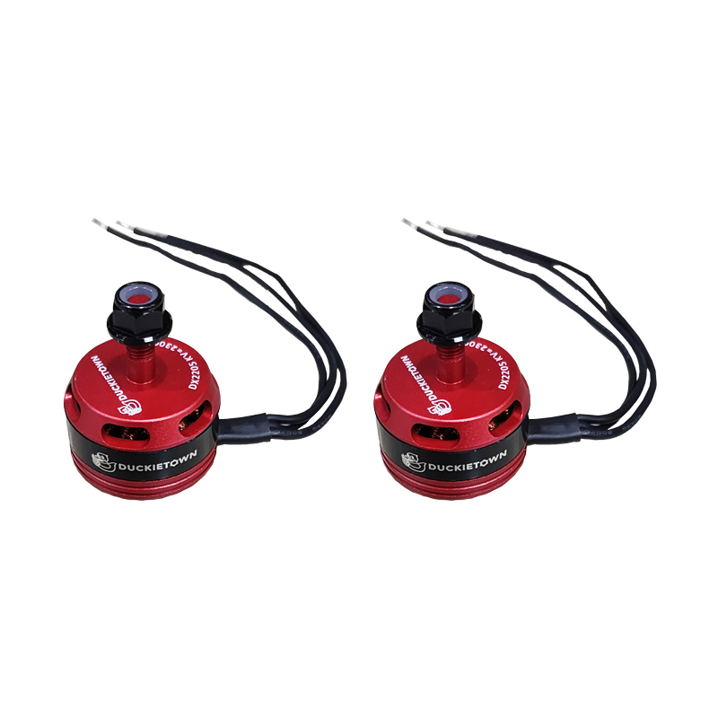
Fig. 15 Brushless DC Motors (Counter-clockwise - CCW).#
The Duckiedrone mounts four LHI DX2205 brushless DC motors. These racing drone motors feature a motor constant of 2300 KV, an M5 shaft diameter, M3 mounting holes, and a weight of roughly 28 g each.
Note that there are two pairs of motors, distinguishable by the color of the top nut.
Note
Black nuts are for motors that spin in the counter-clockwise (CCW) direction.
If you try to unscrew the top nuts, you will notice how they have opposite threads. This is to prevent the nuts from coming off (along with the propellers) during flight.
Motors (CW)#
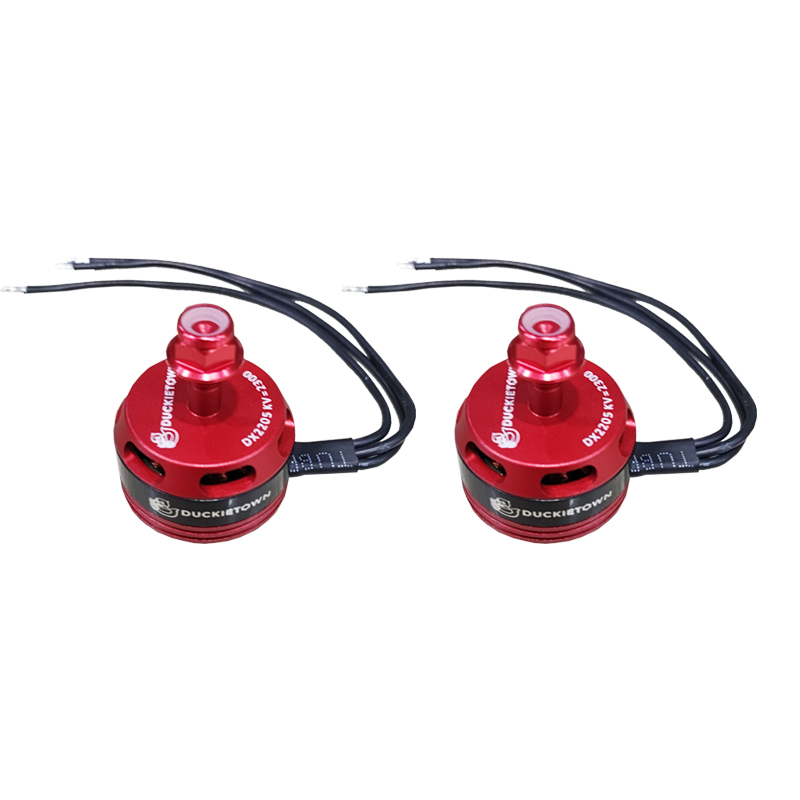
Fig. 16 Brushless DC Motors (Clockwise - CW).#
The Duckiedrone DD24-B mounts four LHI DX2205 brushless DC motors. These racing drone motors feature a motor constant of 2300 KV, an M5 shaft diameter, M3 mounting holes, and a weight of roughly 28 g each.
Note that there are two pairs of motors, distinguishable by the color of the top nut.
Note
Red nuts are for motors that spin in the clockwise (CW) direction.
If you try to unscrew the top nuts, you will notice that they have opposite threads. This is to prevent the nuts from coming off (along with the propellers) during flight.
Propellers (CW and CCW)#
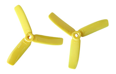
Fig. 17 Propellers (CW and CCW).#
The Duckiedrone mounts four Diatone polycarbonate 4040, 4 x 4 in three-bladed propellers (“props”), each weighing 3.5 g.
The box contains a full spare set, i.e., 2x CW and 2x CCW props.
As for the motors, it is important to note that one set of these propellers is designed for clockwise (CW) motor operations, while the other is designed for counter-clockwise (CCW).
To distinguish CW from CCW propellers, find the arrows embossed on the backside, as shown in Propellers (CW and CCW)..
Battery#

Fig. 18 The Duckiedrone battery.#
The battery provides power for the Duckiedrone to operate, and is therefore essential to autonomous operations.
The Duckiedrone battery is a Lithium-Ion Polymer (LiPo) battery (LiPo basics on Wikipedia) with the following technical specifications:
Cells: 4
Output Voltage:
14.8 VCapacity:
1500 mAhDischarge Rating:
35CWeight:
178 gDimensions:
76 x 35 x 33 mm
See the Rogers Hobby Center LiPo Guide to learn what each number means.
Attention
Before doing anything with the Duckietown battery, see the Duckietown Safety Guidelines.
Warning
Lithium-Ion batteries are fire hazards and must be handled with care.
If for any reason your battery looks punctured or otherwise damaged, do not use it and dispose of it immediately.
You can learn how to safely dispose of a LiPo battery, e.g., here: Oscar Liang’s Guide on Disposing LiPo batteries.
The Duckietown battery connects to the Duckiedrone through a 10 cm long XT60 connector and should be charged using the provided battery charger.
Battery charger#
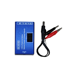
Fig. 19 Lithium-Ion battery charger.#
This battery charger provides a safe charging interface for the LiPo battery. It connects on one side to the battery and on the other to a stable power source (e.g., a wall outlet) through the battery charger adapter.
Operating Voltage Range:
9-16 V DCCell Type Supported: 2-4 cells Li-Ion/Li-Poly
Max Charge Power:
25 WCharge Current:
1500 mACharge Accuracy:
±10 mVBalance Current:
1000 mAMaterial: Metal Case and Voltage Display
Battery charger adapter - 12V 2A US plug#
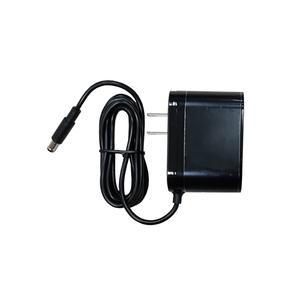
Fig. 20 Duckiedrone battery charger adapter (12 V, 2 A).#
This 12 V, 2 A power adapter, provided with a US wall plug, connects to the battery charger to deliver charge to the battery when needed.
Duckiedrone HUT - v1.2#
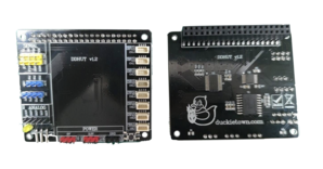
Fig. 21 The Duckiedrone HUT connects the Duckiedrone embedded systems to the Raspberry Pi, and provides a playground for circuit testing.#
The Duckiedrone HUT (yes, HUT, not HAT) is a board that acts as a hub for connections between the various peripherals of the Duckiedrone, such as sensors and the flight controller, and the onboard Raspberry Pi.
It supports the placement of a breadboard to provide a “playground” for additional prototyping or pedagogical experiences, such as adding status LEDs.
Breadboard - Yellow, 45x35mm#
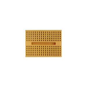
Fig. 22 Duckiedrone HUT breadboard.#
This is a prototyping breadboard with two-sided tape on the back. Attach it in the appropriate empty region on the top of the Duckiedrone HUT. See Wikipedia’s breadboard article for more information about using breadboards.
Flight Controller & ESC stack#
The Flight Controller (FC) and Electronic Speed Controller (ESC) - foreword#
The Flight Controller (FC) is the low-level brain of the Duckiedrone, tasked with transforming high-level decisions, e.g., “go faster”, into actual commands to the motors. The FC hosts an Inertial Measurement Unit (IMU), which measures linear acceleration and angular velocity at high frequency (~200 Hz). Depending on the board, it may also include a barometer, which estimates altitude from atmospheric pressure.
Overall, the FC is an essential component of every drone, even when another computational unit is available onboard (e.g., the Raspberry Pi, as in the case of the Duckiedrone). This is because the dynamics of a drone are much faster than the capability of a Raspberry Pi to deliver commands, e.g., to execute route corrections, especially when the Raspberry Pi is tasked with many other processes as well, such as visual perception.
The Electronic Speed Controller board, which stacks with the FC and is conveniently included in this same box, transforms speed signals for the motors from the FC into lower-level (PWM) signals that make the motors spin.
This FC and ESC stack includes the power distribution circuitry as well, receiving power directly from the battery through an XT60 connector and appropriately regulating (adjusting voltage output and stability) it before providing it to various peripherals.
Note
There are two flight-controller and ESC stack options for the Duckiedrone DD24 family:
SpeedyBee F405 V3/V4 (50 A/55 A) – shipped with the first (DD24) revision kits.
Mamba F405 MK2 V2 (60 A) – shipped with the second (DD24‑B) revision kits.
Both boards share similar functionalities. In this manual, which is dedicated to the ente software distribution for the Duckiedrone, we assume that you are flying one of the latest Duckiedrone DD24-B revisions.
The SpeedyBee flight controller is no longer supported in ente but is still supported in daffy.
Before starting the assembly of your Duckiedrone, make sure to identify which flight controller is in your box, as the assembly instructions are slightly different.
The Duckiedrone DD24-B uses a Mamba F405 MK2 V2 flight controller with a BLHeli_S 3-6S 60A ESC, with details provided in The Mamba FC and BLHeli_S ESC datasheet..
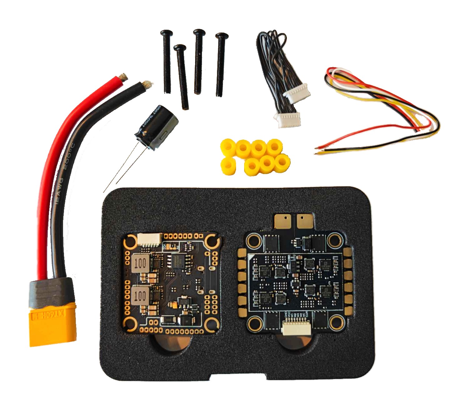
Fig. 23 The Mamba FC and BLHeli_S ESC stack.#
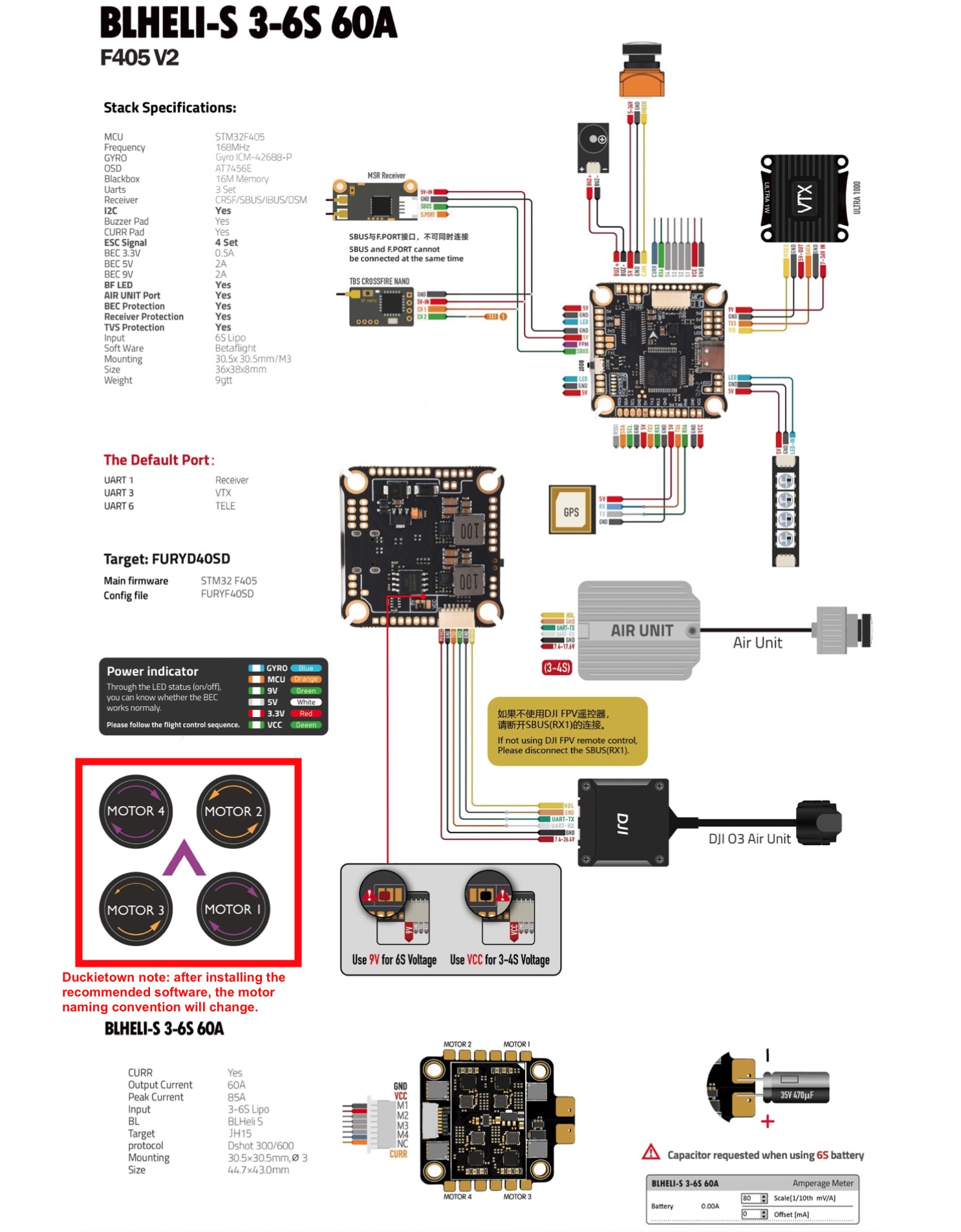
Fig. 24 The Mamba FC and BLHeli_S ESC datasheet.#
Attention
The motor naming convention shown in the datasheet will change once PX4 software is installed. See Motor configuration for details.
The Duckiedrone DD24 uses a SpeedyBee F405 V3 50A, with details provided in The F405 V3 flight controller and ESC stack box components and specifications..
Attention
The SpeedyBee flight controller is no longer supported in ente but is still supported in daffy.

Fig. 25 The Flight Controller (FC) and Electronic Speed Controller (ESC) stack.#
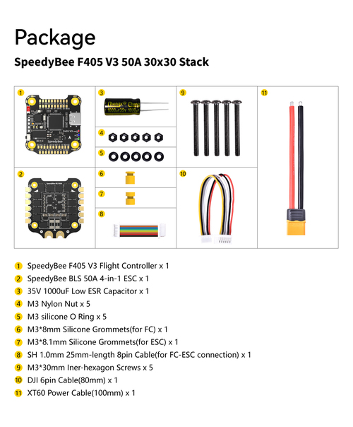
Fig. 26 The F405 V3 flight controller and ESC stack box components and specifications.#
Identifying your flight controller#
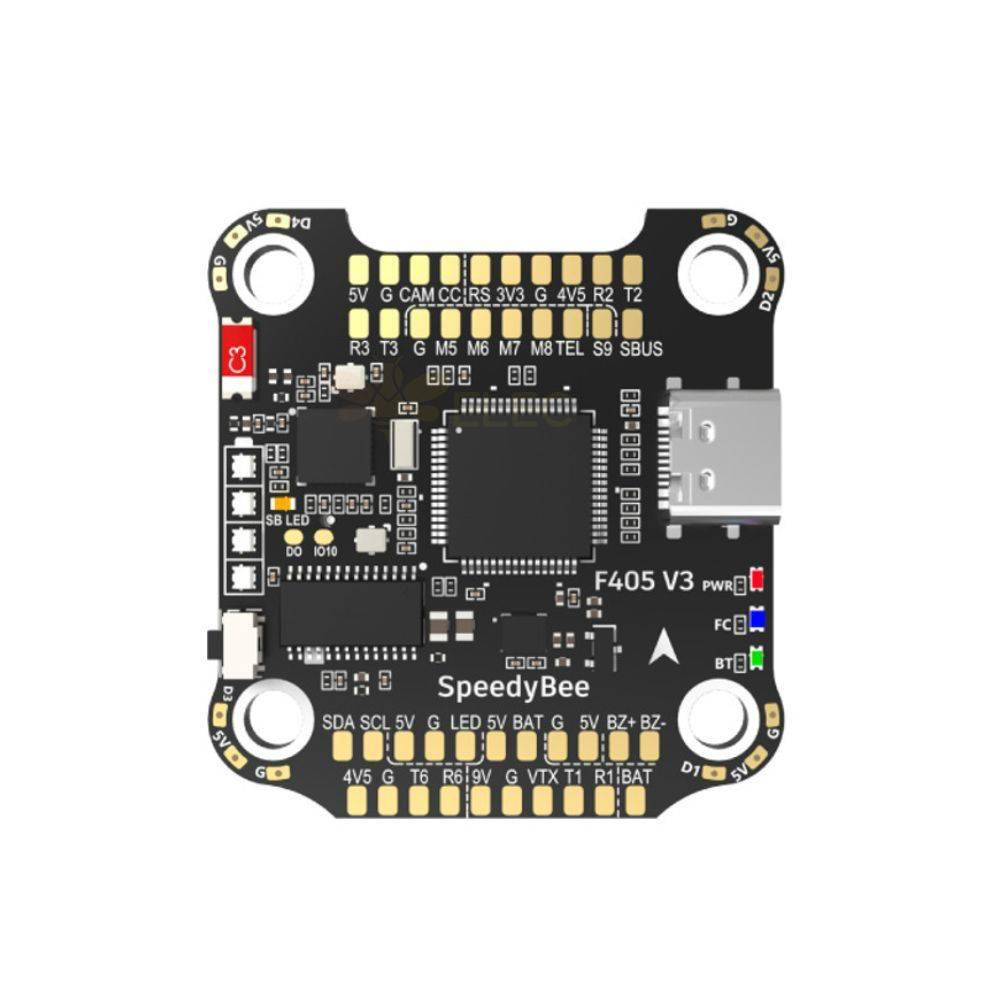
Fig. 27 SpeedyBee F405 V3/V4 (top view).#
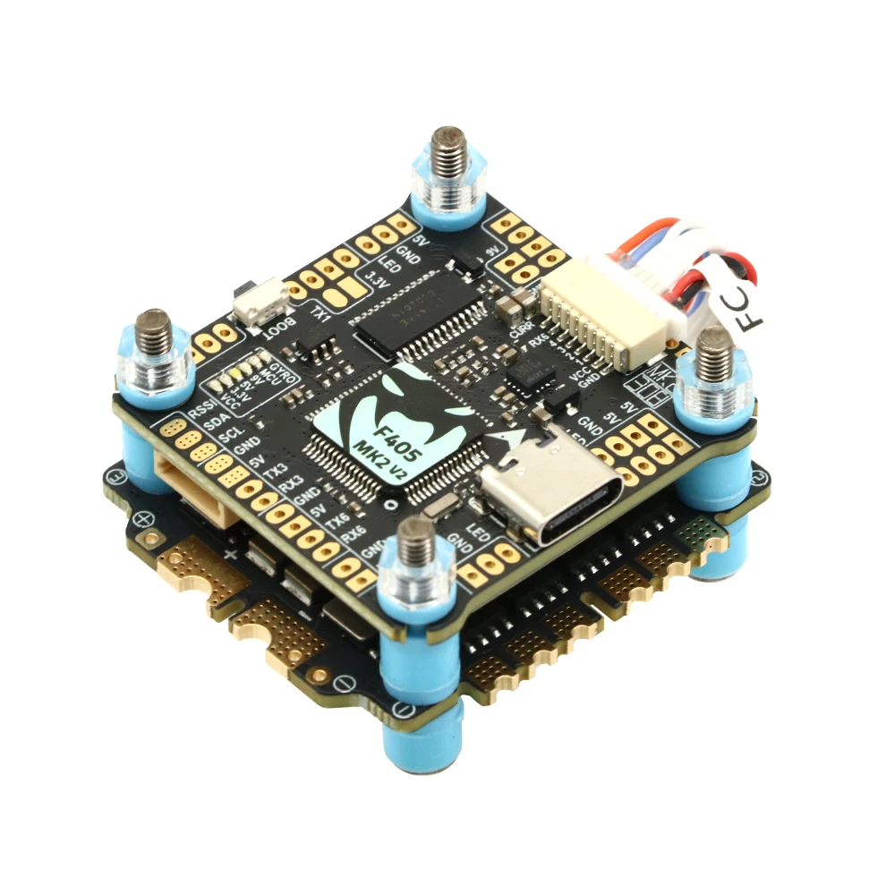
Fig. 28 Mamba F405 MK2 V2 (top view).#
Use the connector layout and the type of soldering pads to recognize your board:
SpeedyBee – only surface soldering pads.
Mamba – through-hole soldering pads.
Attention
The SpeedyBee flight controller is no longer supported in ente but is still supported in daffy.
Buzzer#
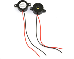
Fig. 29 The buzzer notifies the user when the battery voltage is lower than a certain threshold.#
The Duckiedrone box includes a buzzer. Buzzers emit loud noises when the measured output battery voltage is less than a certain threshold, indicating that the battery is about to be completely discharged. It is a good idea to land the Duckiedrone when hearing the buzzer buzz.
Cables#
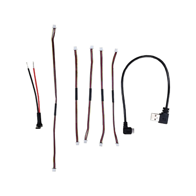
Fig. 30 Duckiedrone cables.#
The Duckiedrone DD24-B box includes:
1x USB-A-to-USB-C cable (with data) -
23 cmplus the length of its connectors, angled: FC to Raspberry Pi connection1x USB-C power cable (power only) -
8 cmwires plus a1 cmexposed wire and2 cmconnector: FC to Raspberry Pi connection4x 4-pin JST
1.5 mmconnectors (both ends) -15 cm: ToF sensor to HUT connections1x 4-pin JST
1.5 mmconnectors (both ends) -23 cm: ToF sensor to HUT connection
Heat sink kit#
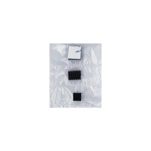
Fig. 31 Heat sinks mount on the Raspberry Pi and help dissipate heat and lower the temperature of the board.#
Heat sinks are simple passive convective elements that stick to specific locations on the Raspberry Pi. Heat sinks help reduce the temperature of the Raspberry Pi, preventing it from automatically going into protection mode and partially shutting down computational resources.
Fan#
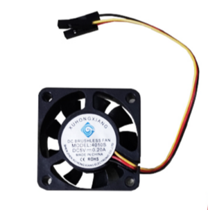
Fig. 32 PWM fan for Raspberry Pi temperature control.#
This fan is used to cool down the Raspberry Pi. It is a PWM fan, meaning the speed at which it spins can be controlled.
PWM speed control, 3-pin Dupont connectors
Size:
40 x 40 x 10 mm85 mmlong cables
Header jumpers - 2.54mm spacing, black#
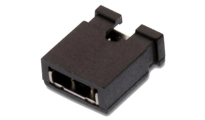
Fig. 33 Jumper for Wi-Fi mode manual toggling.#
This 2.54 mm jumper is used to short (i.e., connect) pins on the HUT. This is useful, e.g., to activate different Wi-Fi modes.
Velcro strips#
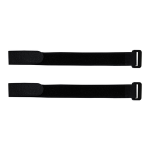
Fig. 34 Velcro strips.#
Velcro strips are used for cable management and securing components, such as the battery, to the Duckiedrone’s chassis. The Duckiedrone box contains:
2x
25 cmblack Velcro strips
Chassis#
The Duckiedrone’s chassis is a custom-designed 2.5 mm-thick carbon-fiber sandwich design with the following components.
Bottom Plate#
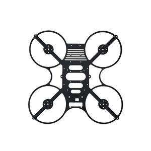
Fig. 35 Duckiedrone chassis: bottom plate.#
The bottom part of the chassis provides the main surface for mounting components, such as the motors, the electronics, the battery, and more.
The chassis has a square design with each side measuring 27.2 cm.
Top Plate#
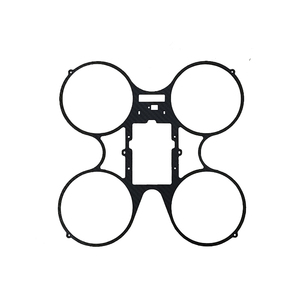
Fig. 36 Duckiedrone chassis: top plate.#
The top chassis plate has the same outer dimensions as the bottom plate (27.2 cm per side), and its main function is to provide structural stability to the Duckiedrone.
Other chassis components#
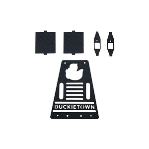
Fig. 37 Duckiedrone chassis: other components.#
Other chassis components include:
2x ToF sensor vertical supports: for mounting side viewing ToF sensors
2x Fan duct walls: to improve thermal control efficiency of the fan
1x Battery support plate: to hold the battery.
Camera mount with ToF sensor support#
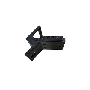
Fig. 38 Camera mount with integrated Time-of-Flight sensor mounting support.#
This chassis component mounts on the bottom plate and is used to hold the Duckiedrone’s camera and front-facing ToF sensor. It places the camera at a 60-degree angle. Coupled with the camera’s 160-degree field of view, it allows the Duckiedrone to see both underneath and in front at the same time.
Landing Gear - 3D printed v1.1#
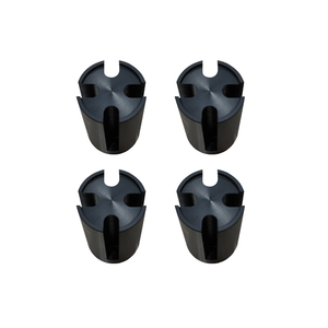
Fig. 39 Landing gear.#
Landing gears mount under each motor and support the Duckiedrone when landing.
Landing Pads#

Fig. 40 Rubber landing pads.#
These rubber landing pads mount under the landing gears and provide a softer landing experience.
Bits and Pieces (Screws, nuts, standoffs)#
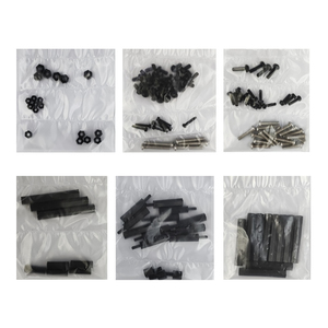
Fig. 41 Screws, nuts and standoffs.#
The Duckiedrone box includes a host of “bits and pieces”, including spares of each:
Screws (number and spares)
(22+2)x Nylon (M3x6) - 16x chassis, 2x securing battery, 4x forward battery supports
(3+1)x Nylon (M3x10) - 3x camera mount
(16+2)x Metal (M3x14) - 16x motors and landing gears
(4+1)x Metal (M3x20) - 4x FC
(11+2)x Nylon (M2.5x8) - 4x HUT, 5x ToF sensors, 2x aft battery supports, 2x Raspberry Pi stack
(6+1)x Nylon (M2x10) - 4x camera, 2x buzzer
Nuts
(5+1)x Nylon (M2.5) - 5x ToF sensors
(6+1)x Nylon (M2) - 4x camera, 2x buzzer
(5+1)x Nylon (M3) - 2x securing battery, 3x camera mount
Standoffs
(2+1)x Nylon (M2.5x40+6 MF) - 2x battery plate and Raspberry Pi standoffs
(4+1)x Nylon (M2.5x20+6 MF) - 4x Raspberry Pi and bottom plate
(4+1)x Nylon (M2.5x15+6 FF) - 4x Raspberry Pi and HUT
(8+2)x Nylon (M3x35+6 FF) - 8x chassis
(2+1)x Nylon (M3x40+6 FF) - 2x forward battery supports
(2+1)x Nylon (M3x6+6 MF) - 2x fan
Wrench#
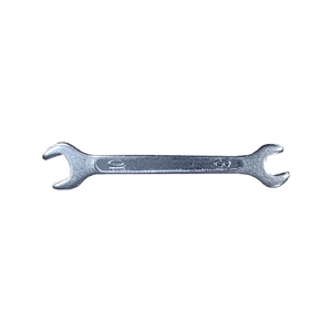
Fig. 42 Wrench (8 mm) for tightening motor top nuts.#
This 8 mm wrench is provided to tighten the motor-prop nuts. We really do not want those to come off while flying.
Screwdriver - Cross#
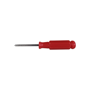
Fig. 43 Cross screwdriver.#
This simple cross screwdriver drives all the screws in the box.
Camera Calibration pattern#
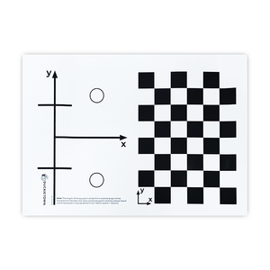
Fig. 44 Duckiedrone (and Duckiebot) camera calibration pattern.#
This checkerboard pattern is used to calibrate the Duckiedrone camera.
Duckietown Duckies#
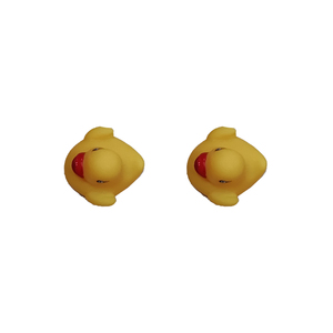
Fig. 45 Duckietown duckies.#
Duckietown duckies are non-functional yet essential to the operations of the Duckiedrone. Make sure to always have at least one duckie onboard.
Duckietown Stickers#

Fig. 46 Duckietown stickers.#
Duckietown stickers look great on your laptop, and notify others of your Duckietown training.
Duckiedrone instruction card#

Fig. 47 Duckiedrone DD24 instruction card.#
This instruction card provides links to the Duckietown website and the Duckietown get started page.