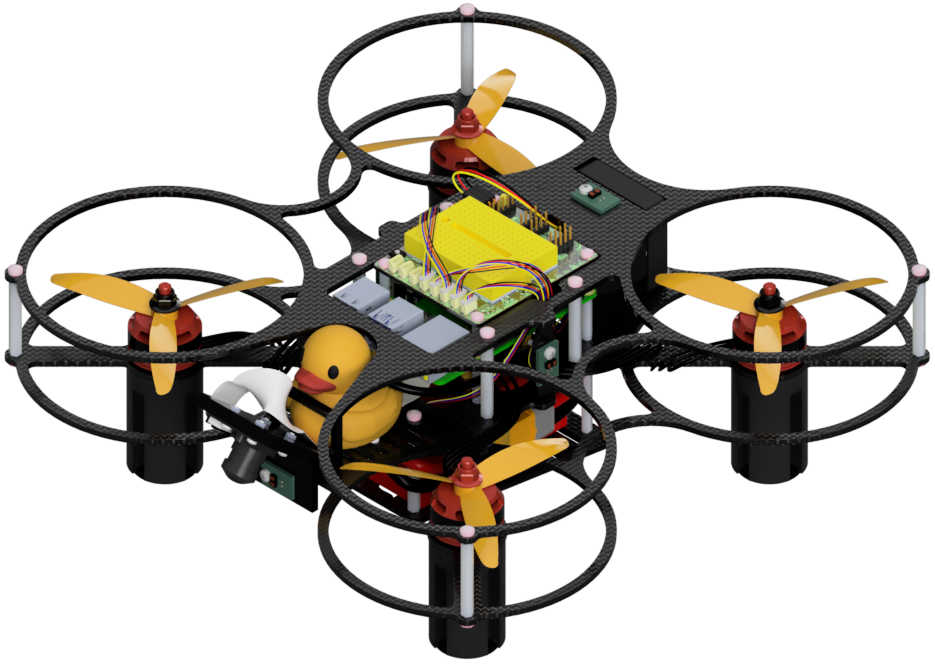
Duckiedrone DD24-B assembly instructions
What you will need
An Duckiedrone
DD24-Bbox: get a DuckiedroneA
DD24initialized SD card:
What you will get
An assembled Duckiedrone model
DD24-B
Warning
🚧 This manual describes the ente software version of the latest Duckiedrone build, and is currently work in progress. 🚧
Pages marked with this warning are actively being worked on.
The stable release to date is the daffy Duckiedrone operation manual.
Duckiedrone DD24-B assembly instructions#
Attention
There is an error in steps 31–37 of the assembly process.
Please connect your ToF sensors in this order:
The bottom Time-of-Flight (ToF) sensor must be connected to the port labeled
CHL0.The left Time-of-Flight (ToF) sensor must be connected to the port labeled
CHL1.The right Time-of-Flight (ToF) sensor must be connected to the port labeled
CHL2.The top Time-of-Flight (ToF) sensor must be connected to the port labeled
CHL3.The front Time-of-Flight (ToF) sensor must be connected to the port labeled
CHL4.
Please make these adjustments manually while we work on updating the 3D assembly tool.
Attention
The flight controller and PDB included with the DD24-B differ slightly from those depicted in the 3D assembly tool.
Step 2:
Ensure the PDB is oriented with the white 6-pin connector facing downward, and the silkscreen labels M1, M2, M3, and M4 facing upward.
Fig. 50 ESC board orientation — this side must face upward.#
Step 10 and Step 16: Refer to the following schematic for the correct soldering connections on the flight controller:
Fig. 51 Flight controller soldering connections.#