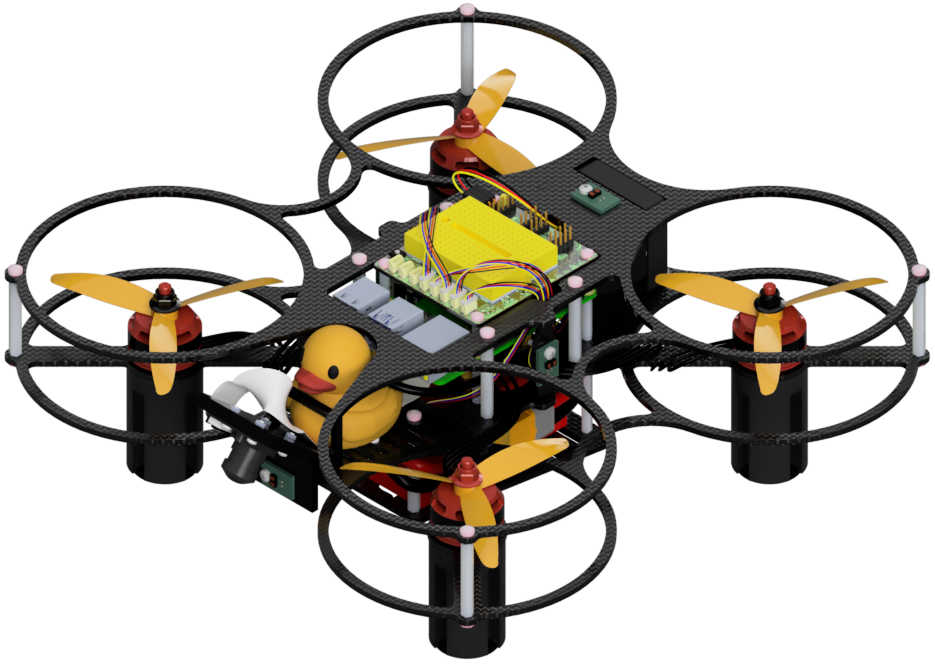
Motor configuration
Contents
What you will need
A base station computer with QGroundControl installed
An initialized Flight Controller running PX4 with the parameters already loaded
ESCs already flashed with Bluejay
The Duckiedrone battery and a long data-capable USB-A-to-USB-C cable
What you will get
A Flight Controller that drives the four motors in the correct order, each turning the right way
Motor configuration#
The flight controller needs the motor order and spin direction to match the configured quad-X layout. If either is wrong, the Duckiedrone will not fly and may flip over the instant it leaves the ground. Work through this page slowly.
Warning
Keep the propellers off the entire time while following instructions on this page.
Attention
Make sure the battery is charged, and connect it to the Duckiedrone, since the motors need power to spin.
1. Connect the Flight Controller to the base station#
Connect the flight controller to your base station with the data-capable USB-A-to-USB-C cable. You may need to use an extension or an adapter depending on your setup.
Then, on your base station open QGroundControl. After a few seconds it will automatically detect the vehicle, as described in the flight-controller connection procedure. Wait until the top toolbar shows the vehicle as connected before proceeding.
2. Motor Order#
Open the Actuators page from the left sidebar in QGroundControl. This page is where PX4 maps each physical motor on the frame to an output on the flight controller.
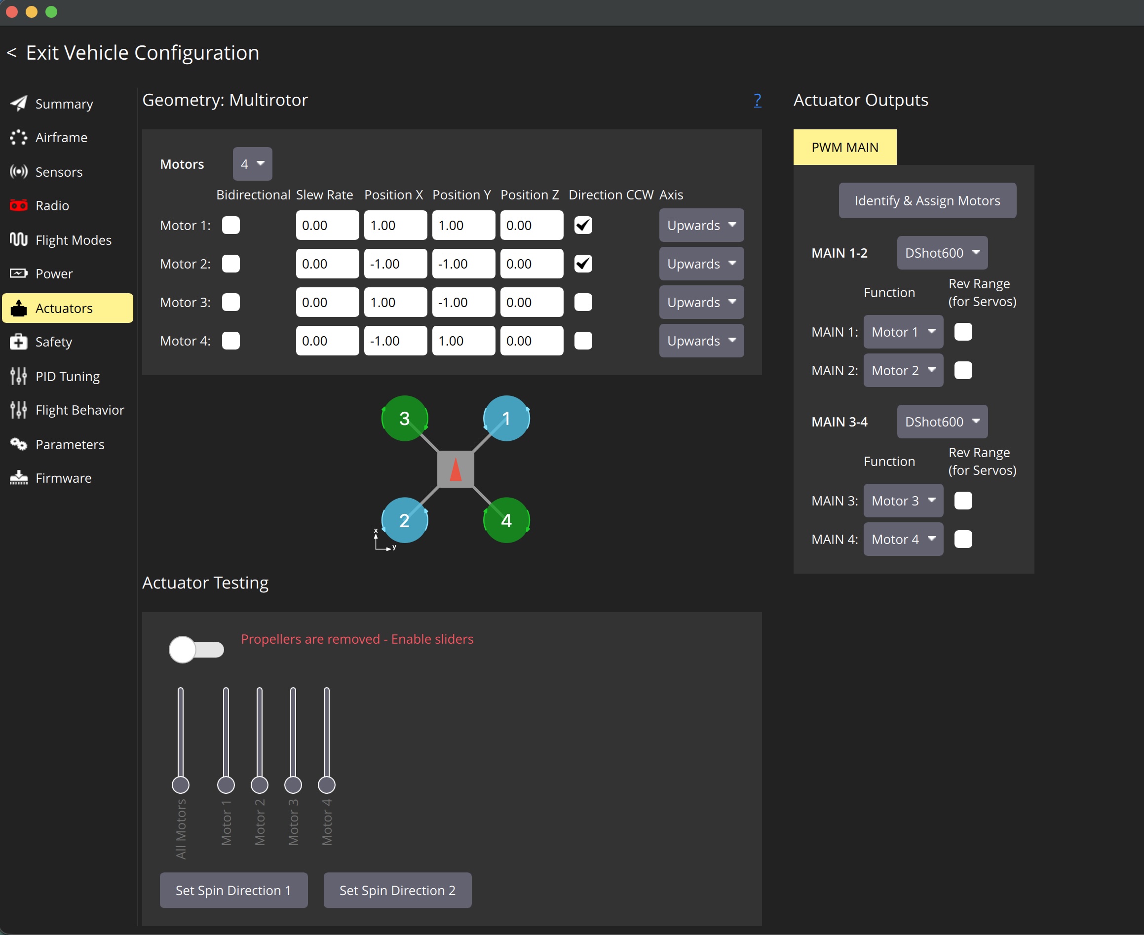
Fig. 66 QGroundControl Actuators page showing motor numbering, positions, spin configuration, and ESC communication protocol.#
PX4 has a fixed idea of where each motor belongs on a quadcopter. When it refers to Motor 1, …, 4, it means a specific corner of the frame. The Duckiedrone DD24-B frame is a “quad X”, and the numbering PX4 expects is:
Motor 1 is at the front right.
Motor 2 is at the rear left.
Motor 3 is at the front left.
Motor 4 is at the rear right.
The front is the direction the Duckiedrone flies forward. It aligns with the arrow in the QGroundControl diagram and with the direction of the camera and duckie on the Duckiedrone.
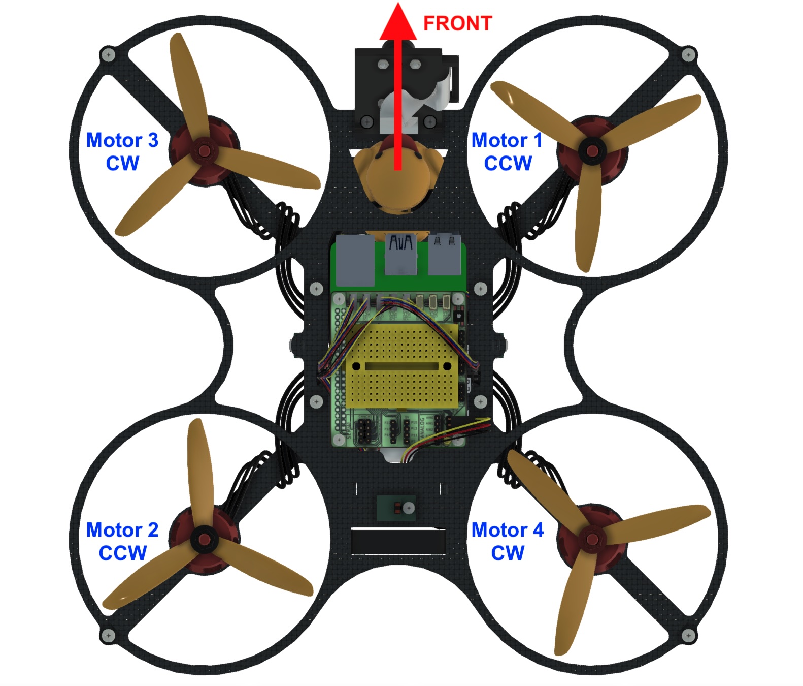
Fig. 67 Motor configuration on the Duckiedrone.#
Identify and label each motor. QGroundControl can walk you through this. On the Actuators page, start the motor identification routine. It spins one motor at a time and asks you to select the motor that spun. QGroundControl then reassigns the outputs to match the selected order.
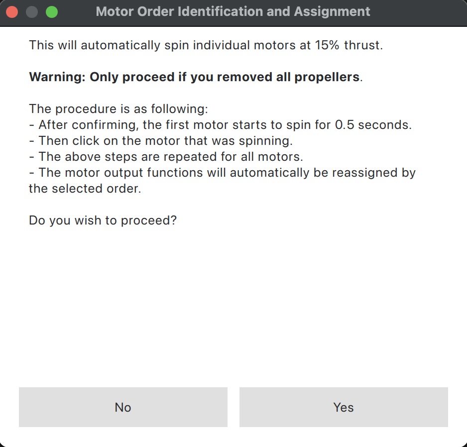
Fig. 68 QGroundControl automatic motor-identification procedure.#
Sometimes the identification popup does not appear. If that happens you can do the same thing by hand. Turn on the switch that enables the motor sliders on the Actuators page, then move one slider by a small amount and watch which motor on the frame spins. Note the corner that moved, then assign that output to the corresponding motor function in the interface. Repeat for all four motors until every number lines up with the real position on the frame.
Tip
Move the sliders only a little and keep the propellers off. You need just enough movement to see which motor turns.
Note
The motors will spin only if the Duckiedrone battery is plugged in.
3. Motor Spin Direction#
Once every motor is on the correct number, check which way each one turns. On the Duckiedrone, the “props-in” motor layout expects:
Motor 1: front right, black nut, spins counter-clockwise.
Motor 2: rear left, black nut, spins counter-clockwise.
Motor 3: front left, red nut, turns clockwise.
Motor 4: rear right, red nut, turns clockwise.
Spin each motor from the Actuators page and compare its direction against the list above. Make a note of any motor that turns the wrong way.
Note
The Set Spin Direction controls appear after DShot is selected and the motors are assigned. This procedure assumes the Bluejay-flashed ESCs from Initializing the ESCs.
Alternatively, reverse a motor by sending a PX4 DShot command to its ESC. Open the terminal inside QGroundControl by going to Analyze Tools and then MAVLink Console. This opens the PX4 shell.
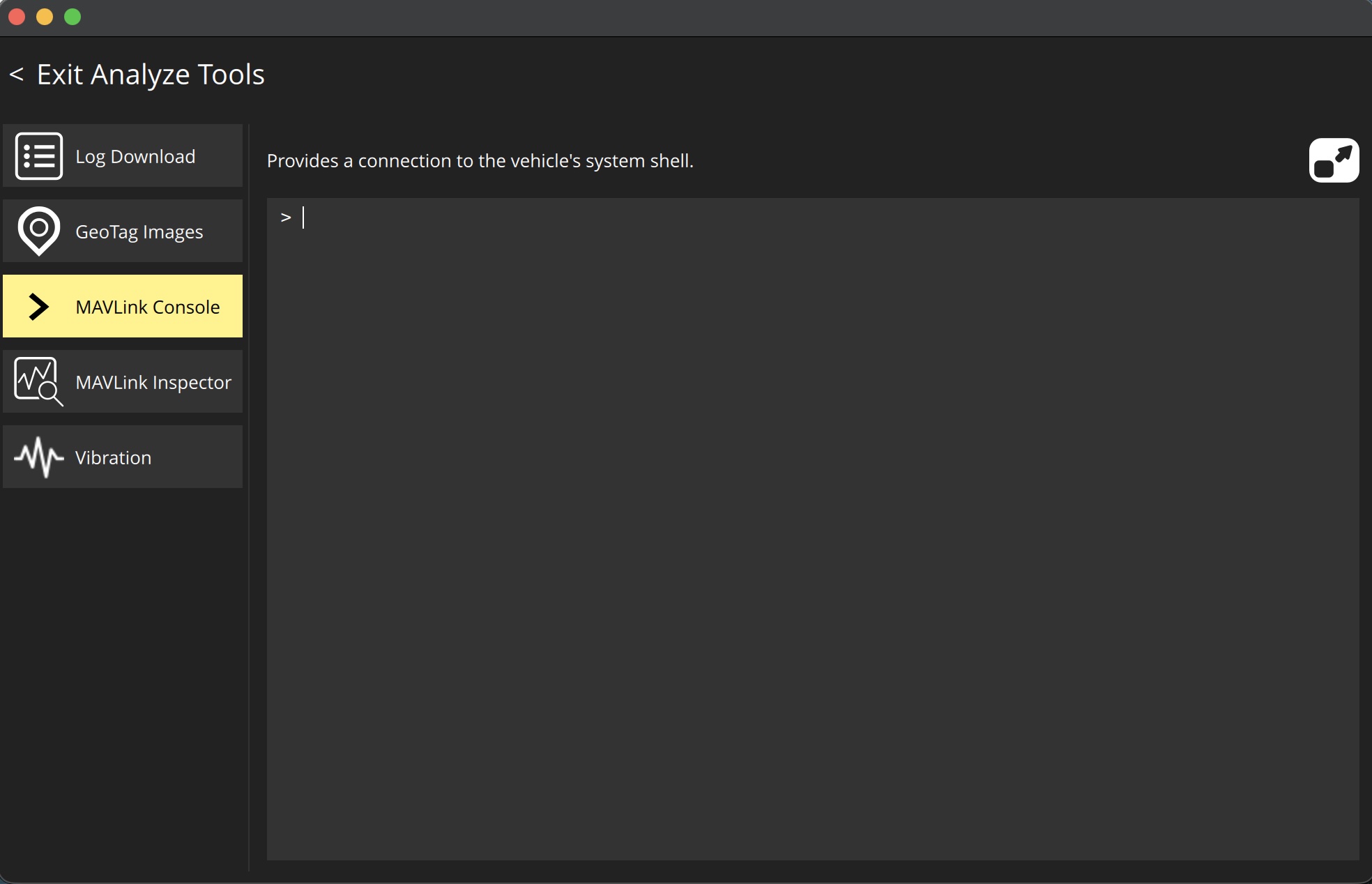
Fig. 69 QGroundControl MAVLink Console.#
In the shell, reverse a motor by its number. For example, to reverse Motor 3 you run:
dshot reverse -m 3
Go back to the Actuators page and spin that motor again to confirm it now turns the right way.
When the direction is correct, save it so it survives a reboot:
dshot save -m 3
Finally, disconnect and reconnect the battery to power cycle the ESC. Once it comes back the new direction is locked in. Repeat and save for every motor that was turning the wrong way, then spin all four one last time to confirm they match the nominal layout.